OPERATING INSTRUCTION MANUAL MODEL 8760CLP TOTAL FREE CHLORINE & pH ANALYZER REV. 0 AquaMetrix Inc. 1245 Maple Hill Ct, Unit 7 Newmarket, ON Canada, L3Y 9E8 Tel: (800) 742-1413 (905) 954-0841 Fax: (905) 954-0415 www.aquametrix.com N116-58 R.
AQUAMETRIX INC. Contents Contents ………………………………………………. 8760CLP Menus……………………………………… INTRODUCTION……………………………………. General ………………………………………… Features…………………………………………. Specifications……………………………………. INSTALLATION……………………………………. Analyzer Mounting………………………………. 8760CLP Component Identification……………... Analyzer Wiring………………………………….. Sensor Mounting…………………………………. Sensor Wiring…………………………………….. Instrument Shop Test Startup…………………….. STARTUP…………………………………………….. Analyzer Startup Tests………………………….
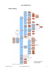
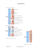
AQUAMETRIX INC. 8760CLP Menus Illustration 1: Menu overview 1-800-742-1413 www.aquametrix.
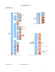
AQUAMETRIX INC. 8760CLP Menus Illustration 3: Timer menu Illustration 2: Configuration menu 1-800-742-1413 Illustration 4 Alarm menu www.aquametrix.
AQUAMETRIX INC. Illustration 5: Internal data log menu Illustration 6: Serial menu 1-800-742-1413 www.aquametrix.
AQUAMETRIX INC. INTRODUCTION The model 8760CLP is AquaMetrix’s industrial quality remote operational total free chlorine and pH analyzer, designed to provide maximum flexibility, reliability, and ease-of-use. The model 8760CLP analyzer has been designed to include a pH input to measure sample pH for continual pH compensation ― ideal for samples with fluctuating pH values. Temperature compensation is obtained via a temperature sensor in the chlorine sensor.
AQUAMETRIX INC. General The 8760CLP is supplied in a corrosion resistant IP65 (NEMA 4X) watertight, dust-tight case. The analyzer measures the sensor signal corresponding to the actual chlorine with respect to the sample pH and temperature. The analyzer digitizes the signal for maximum accuracy, conditions it and then sends it out as a digital output and/or on 4 mA to 20 mA outputs. The model 8760CLP comes as a complete sample conditioning system.
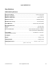
AQUAMETRIX INC. Specifications Specifications Analyzer; 8760CL PROPERTY Display Display Ranges Keypad LED’S Analyzer Dimensions Panel Dimensions Weight Shipping Weight Shipping Dimensions PROPERTY Temperature Environment Ratings Electrical Ratings Electrical Requirements 1-800-742-1413 Physical Data CHARACTERISTIC Four LCD digits, 1.5 cm (0.6 in) displays for total free available chlorine (tFC1) and diagnostic information (back –lit display optional) Total free available chlorine (tFC1): 0.
AQUAMETRIX INC. Specifications Analyzer 8760CL Operational Data PROPERTY Accuracy Precision Response Time CHARACTERISTIC Chlorine: ±0.02 mg/L PH: ±0.04 ph units Temperature: ±0.1 C Chlorine: ±0.01 mg/L PH: ±0.02 pH units Temperature: ± 0.1 °C 90% within 5 s (default), function of flow and temperature Damping adjust: 3 to 99’s Temperature Compensation Sample Conditions Automatic temperature compensation via 1000 Ω Pt RTD. Auto: -5 °C to 105 (23.0 °F to 221 °F) Manual -5 °C to 105 (23.
AQUAMETRIX INC. Specifications AM-A2104033 pH Sensor Measurement Range.........................................................................................0 pH to 14 pH units Minimum Temperature.................................................................................................0 °C (32 °F) Maximum Temperature..........................................................................................100 °C (212 °F) Maximum Pressure..............................................................
AQUAMETRIX INC. Specifications AM-A2104034 Chlorine Sensor Measurement Range Free Available Chlorine (HOCl)....................................................................0.00 mg/L to 2.00 mg/L Total Free Available Chlorine (HOCl + OCl⎯)................................................0.00 mg/L to 5.00 mg/L Minimum Temperature.................................................................................................0 °C (32 °F) Maximum Temperature...................................................
AQUAMETRIX INC. INSTALLATION Analyzer Mounting The model 8760CLP comes as a complete sample conditioning system. The analyzer is mounted on a CPVC panel with a dual flow cell containing the pH and chlorine sensors. The sample conditioning system includes a pressure regulator valve, sample point and atmospheric drain. The only installation requirement of the user is to mount the panel and supply plumbing to the inlet and from the outlet.
AQUAMETRIX INC. ANALYZER WIRING Please refer to drawing D5040276 and perform the following: 1. The 8760CLP requires 115 VAC or 230 VAC power to be hooked up to TB400. Power consumed is less than 1 A so generally 16 gauge wire is OK (consult local electrical codes for verification). For stable operation, the microprocessor needs a good earth ground. CAUTION: Confirm that the 115/230 VAC switch is correctly set for your feed. 2. If required, connect the two relay contacts; as supplied, they are not powered.
AQUAMETRIX INC. Instrument Shop Test Startup 1. Apply 115/230 VAC power to the analyzer. 2. Hook up the chlorine sensor to bottom of analyzer via 5-pin DIN connector. Ensure that the shorting strap on the sensor connector is removed (refer to illustration 8). Keep shorting jack for future use. 3. With the chlorine sensor in air, the 8760CL analyzer should come up reading 0.0 ppm ± 0.05 ppm. 4.
AQUAMETRIX INC. STARTUP If the analyzer is new and has not been installed, follow the procedures described in Installation and Configuration of Program before mounting. Mounting and wiring procedures for new installations vary with equipment options — see drawing section for instructions. If the analyzer has been previously installed, all that is required is to attach the electrode to the analyzer and then to turn on the power.
AQUAMETRIX INC. Easy to use Menu The layout of the program is shown in the menus starting on page 3. Remembers Where You Were The analyzer remembers where SAMPLE is. The sample display is home base for the program. The program also remembers which menu selections were used last and loops around the columns. The menu can be accessed using the arrow keys to find any parameter then press SAMPLE to return to the displayed reading. Then, using the Right arrow key return to exactly where you were.
AQUAMETRIX INC. Arrow Keys The four arrow keys on the keypad are used to move around in the menu. Example: Press SAMPLE to make sure that display is at home base. Press the Right arrow key. One of the prompts in the column starting with [out] will be displayed. Use the Up or Down arrow keys to display the prompt above or below. If the prompt at the top or the bottom is displayed, the program will loop around. Press the Up or Down key until [AL] is displayed.
AQUAMETRIX INC. Edit Mode Edit mode is used to change a numeric value or to select between different options. Values and settings that can be edited are identified by the darker shading in the menu. Any frame, which has a white background, cannot be modified. Editing by Selecting a Setting Editing a value is like picking an option from a list; only one item on the list can be seen at a time. To change the setting, press ENTER to go into edit mode. The display will start blinking.
AQUAMETRIX INC. Temperature °C or °F By default, the analyzer will use metric units. This means that temperature will be displayed using degrees Celsius and that the prompt for the temperature input will be [°C]. The analyzer can also use imperial units. For imperial units, temperature will be displayed using degrees Fahrenheit and the prompt for the first temperature input will be [°F] instead of [°C]. In this instruction manual, the temperature input is always identified as [°C] throughout the menus.
AQUAMETRIX INC. APPLICATION INFORMATION Chlorine Chemistry When chlorine gas is dissolved in water, it hydrolyzes rapidly according to equation 1. This reaction occurs very rapidly, in only a few tenths of a second at 18 °C. 1) Cl 2 g H 2 O aq — HOC l aq HCl aq Since HCl (hydrochloric acid) is a strong acid, the addition of gaseous chlorine to water results in a lowering of the pH due to the acidic HCl by-product. The important product of reaction (1) is HOCl or hypochlorous acid.
AQUAMETRIX INC. In waters between 5 pH and 8.5 pH, the reaction is incomplete and both species are present to some degree. Since H+ is one of the ions that is formed and it's concentration is expressed as pH, it follows that changing pH levels will influence the balance of this reaction and with it the availability of hypochlorous acid for reaction. In a water environment, the water pH will affect the chemistry of chlorine due to it's pH sensitivity. This becomes important as pH rises.
AQUAMETRIX INC. Disinfectant Properties of Chlorine Chlorine is known to be a good disinfectant; it is able to kill living matter in water such as bacteria, cysts, and spores. Exactly how chlorine works to kill is not known. Studies do agree, however, that certain forms of chlorine are more effective disinfectants than others.
AQUAMETRIX INC. 8760CLP CHLORINE MEASUREMENT Introduction Chlorine in water is a measure of the amount of chlorine, usually thought of as a gas, that is dissolved in the liquid. Chlorine is widely respected as a leading chemical for the treatment of water to make it potable or safe to drink. In addition, free available chlorine is often used to control biological agent growth in water filled industrial systems.
AQUAMETRIX INC. CHLORINE SENSOR INSTRUCTIONS The chlorine sensor is designed for simple maintenance. The sensor is robust and will withstand difficult applications when properly applied and maintained. Follow the instructions in this section to promote proper operation.
AQUAMETRIX INC. Assembly of the Chlorine Sensor This procedure should be done over a sink. Protective eye-wear and plastic or rubber gloves are recommended when handling the electrolyte, a salt solution. Wash hands with water if the electrolyte comes in contact with the skin. 1. Galvanic chlorine sensors should have a current drain at all times. Assemble sensor while powered to analyzer OR with a short; coax center to shield.
AQUAMETRIX INC. e) Take the sensor and rinse the fill solution cavity with fresh fill solution, P/N AM-A1100239. Hold the sensor in an upright position with the fill solution cavity facing upwards and fill with P/N AM-A1100239 so that the gold tip is completely covered with liquid. Ensure that there are no air bubbles in the solution. f) Take the assembled toolkit with the larger diameter hole and place over top of the fluid filled sensor tip (refer to illustration 22).
AQUAMETRIX INC. Inserting Chlorine Sensor in the Flow Fitting 1. Inspect the inside of the quick union fitting for any foreign matter and wipe out any dirt which may be inside. It should appear clean, shiny and bright. 2. Install the union ring-nut and push sleeve on the assembled chlorine sensor by sliding it down the lead wire. 3. Check that the sealing O-ring is on the electrode body, on the sensing tip side of the ledge, or in the O-ring groove of the flow cell. 4.
AQUAMETRIX INC. Monthly Maintenance Certain applications may require occasional sensor cleaning. A monthly maintenance check is recommended by visual examination of the sensor cell area. If needed, a soft wipe can be used to blot, plus detergent and water to remove any deposits. Rinse thoroughly after cleaning with water. Run a calibration and return to service if sensor efficiency is above 50 percent.. White silt inside the sensor cap may not cause problems.
AQUAMETRIX INC. Sensor Storage Short Term: Immerse the sensor tip in tap water. Wet storage can be used up to two weeks. If the sensor is not connected to the analyzer, the sensor needs to be shorted. Place the shorting strap across the appropriate pins of the sensor connector (refer to illustration 8). CAUTION: If a wet sensor dries out in storage, it may become damaged beyond repair. Long Term: Disassemble the chlorine sensor tip and pour out the fill solution.
AQUAMETRIX INC. CHLORINE CALIBRATION The 8760CLP chlorine system is calibrated by grab sample; an easy method of standardizing the chlorine measurement without taking the electrode out of the sample. Grab sample standardization method requires the user to determine the actual total free chlorine concentration of the sample using an alternative method.
AQUAMETRIX INC. 6. Remove the fluid-filled ampoule from the cup. Mix the contents of the ampoule by inverting it several times, allowing the bubble to travel from end to end each time. 7. Wipe all liquid from the exterior of the ampoule and wait 1 minute. 8. After 1 minute, use the appropriate comparator to determine the level of chlorine in the sample. Write down the chlorine value.
AQUAMETRIX INC. pH and Temperature impact on Chlorine The measurement of the chlorine concentration is done by the galvanic sensing electrode. However, the chlorine chemistry of the sample will change with both temperature and pH. Illustration 15 shows how the relative concentrations of hypochlorous acid and hypochlorite ion shift with a change in the water pH. This same relationship is also dependent on the temperature of the solution, as the curves will shift with changes in the temperature.
AQUAMETRIX INC. pH SENSOR INSTRUCTIONS Preparation for Use 1. Moisten the pH sensor body with tap water and carefully remove the tape and orange plastic storage cap. Caution should be used in removing this cap; pull straight down. Do not bend the body of the pH sensor. This can result in damage to the internal element. NOTE: Save the lower cap for later use in storage of the pH sensor. 2. Rinse away any deposits on the exposed pH bulb and junction area with tap water. 3.
AQUAMETRIX INC. Monthly Maintenance Remove the sensor from the flow cell, rinse in water, remove any significant deposits, and then check by calibration in 7 pH for offset and then 4 pH or 10 pH buffer for slope. If the calibration turns up a caution or error message in the 8760CL analyzer, then follow the appropriate solution. Also, refer to Troubleshooting section. If the calibration is good, keep a log of the pH offset and slope at each monthly calibration.
AQUAMETRIX INC. Chemical Cleaning of Sensor AquaMetrix offers a pH sensor chemical cleaning kit containing solutions and necessary cleaning items as P/N AM-A1600054. NOTE 1: A suitable place to do chemical cleaning is at a counter or bench with a laboratory sink, with a chemical drain where waste is contained and treated before release.
AQUAMETRIX INC. pH CALIBRATION The pH input is calibrated using one of two methods. A one-point standardization adjusts the electrode offset while maintaining the previous slope. The two-point calibration combines the results of the standardization with the results of the buffer 2 calibration and calculates the slope as well as the offset. A calibration is easily accomplished by selecting an appropriate buffer, placing the electrode in the buffer solution, and letting the analyzer do the rest.
AQUAMETRIX INC. Temperature Dependence of Buffers The pH of a solution is dependent on temperature. To achieve greater accuracy, the temperaturecompensated values for the 4 pH, 7 pH and 10 pH buffers are calculated by AquaMertix analyzers. The graphs show the temperature-dependence of the standard buffers. The TC-curves have been programmed into the AquaMetrix analyzer. The actual pH value of each of the three standard Illustration 31: Temperature compensated pH 4 buffer buffers will be used.
AQUAMETRIX INC. Standardizing — Single-Buffer Calibration Standardizing the analyzer causes the analyzer to calculate the offset for the pH electrode; indicated as [OFFS] in the [PH] menu. The electrode slope value determined during the last buffer 2 calibration will be maintained; indicated as [SLOP] in [PH] menu. 1. Press SAMPLE to display the [tFCl] reading. Press SELECT to reach the main menu, then use the Up or Down arrow keys to display [PH].
AQUAMETRIX INC. Calibrating – Two-Buffer Calibration Calibrating the analyzer involves calculating both the offset and the slope (electrode efficiency) for a particular electrode pair. The electrode slope will be calculated as a percentage of Nernstian response. 1. Calibrate the offset with 7 pH buffer as [buF1], buffer 1, by following the procedure for Standardizing - Single Buffer Calibration. Return to the calibration menu and display [buF2]. Press SELECT to reach the buffer selection menu. 2.
AQUAMETRIX INC. ERROR MESSAGES Detected errors and/or cautions can be displayed by the analyzer. From the main menu select [Err]. If there are no error or caution messages, [NONE] will be displayed, otherwise scroll through the error list using the Up and Down arrow keys. Errors and cautions cannot be removed from this list directly; each error or caution will be removed automatically when appropriate, eg.
AQUAMETRIX INC. Messages for Chlorine Input Error E1.0 Description Reading is offscale. Display shows [+Err]. Causes Solutions The internal A/D converter is at the top of the scale. The analyzer cannot measure higher chlorine values. The analyzer is at the limit of it's measuring capability. Check the sensor setup to ensure that the sensor is operating properly. Service or replace the sensor if necessary. The analyzer needs electronic adjustments. Arrange for servicing. E1.
AQUAMETRIX INC. Messages for pH Input Error Description Causes Solutions E3.1 Electrode has not stabilized after 5 minutes of calibration. E3.2 Electrode has stabilized, but Large offset in electrode. offset > ± 1.3 pH units. This error generated by auto detection of pH 4, pH 7, and pH 10 buffers only. Previous offset is retained. Wrong buffer used for calibration Only pH 4, pH 7, and pH 10 buffers can be detected automatically.
AQUAMETRIX INC. Error + Err - Err Description pH reading off-scale; pH > 14. pH reading off-scale; pH < 0. Causes Solutions Process too caustic for accurate measurement. Verify process. Large electrode offset. Service or replace electrode. Electrode not connected. Connect electrode or check connections. Electrode not responding. Etch glass electrode. Clean reference electrode. Process too acidic to be measured. Verify process. Caution Messages for Alarms Caution Number Description CA7.
AQUAMETRIX INC. DISPLAY PROMPTS [_ . _] Timer menu [+_ . _] Set time for on-cycle [-_ . _] Set time for off-cycle [AL] Alarms [AL.A] Alarm A [AL.b] Alarm B [Auto] Automatic compensation [bAud] Baud rate [buF1] Buffer for standardizing or first buffer for calibration [buF2] Second buffer for calibration [°C] Temperature in degrees Celsius; temperature input; use metric units [CAL] Calibrate [CHIP] Chip.
AQUAMETRIX INC. [ON.OF] [onth] [OPEN] [out] [out1] [out2] [PH] [pH.C] [rtc] [SEC] [SEr] [SEt] [SLOP] [StAr] [StAt] [Stby] [Std.] [tc] [tFCl] [unit] [YEAr] On/off switch Month. Real-time clock setting Normally open alarm contact 4 mA to 20 mA analog output channel Output 1 Output 2 pH input pH compensation Real-time clock Second.
AQUAMETRIX INC. GLOSSARY Electrode Both a sensing and a reference electrode are needed for the analyzer to measure the process. Commonly these are combined into one and referred to as a combination electrode. The temperature sensor may be built into the electrode as well. EPROM Erasable/Programmable Read Only Memory. The EPROM chip holds the program which determines the functioning of 8760CLP analyzer.
AQUAMETRIX INC. CONFIGURATION OF PROGRAM The 8760CL analyzer has been designed with ease-of-use in mind. In most cases the analyzer has been configured to ordered specifications at the factory and no configuration of the analyzer is necessary. However, several hardware options are available and if they are changed the program configuration settings need to be set accordingly for the program to function properly.
AQUAMETRIX INC. Metric or Imperial Units By default the analyzer will use metric units. This means that temperature will be displayed using degrees Celsius and that the prompt for the temperature input will be [°C]. The analyzer can also be made to use imperial units as the preferred unit. Using imperial units, temperature will be displayed using degrees Fahrenheit in the sample menu and the prompt for the temperature input will be [°F] instead of [°C] throughout the program.
AQUAMETRIX INC. OUTPUT SIGNALS Two assignable 4 mA to 20 mA output channels are provided. The user may configure the analyzer to determine which input signal will be transmitted by each 4 mA to 20 mA output channel. Each output channel can be independently configured to transmit a chlorine, pH or temperature signal. The output channels function independent of each other. Each output channel has a separate on/off switch and adjustable low and high span (or scale) adjustments.
AQUAMETRIX INC. ALARM FUNCTIONS Two alarms, alarm A and alarm B, are a standard feature. Each alarm has an alarm contact associated with it which can be used for remote alarm indication or for control functions. The two alarms function independently of each other. Either alarm can independently monitor any of the inputs. Each alarm features an adjustable set-point, userselectable alarm type, and adjustable differential (also called hysteresis).
AQUAMETRIX INC. Manual Alarm Override For normal alarm operation the alarms are said to operate in auto-mode. If the operator wishes to intervene and switch off the alarm contacts temporarily while attending to a problem, the alarms can be switched to manual override using the MANUAL key. In AUTO mode: the green AUTO LED is on and the analyzer alarms will activate and deactivate the relay contact as programmed. Press the MANUAL key to temporarily deactivate the alarm contacts.
AQUAMETRIX INC. High or Low Alarm A high alarm is set when the value of the chlorine, pH or temperature rises above the set-point and is cleared when that value drops to below the set-point minus the differential (refer to illustration 41). A low alarm is set when the value of the chlorine, pH or temperature drops below the set-point and is cleared when that value rises to above the set-point plus the differential (refer to illustration 42).
AQUAMETRIX INC. Fault Alarm A fault alarm for an input will be set when anything goes wrong with that input. Something is wrong with an input if the input is off-scale or an unacknowledged error message exists for that input. Caution messages do not cause a fault alarm. To use an alarm as a fault alarm, select [FUNC] from the alarm menu, then select [Flt]. To enable the alarm, make sure the on/off switch is set to [on].
AQUAMETRIX INC. TROUBLESHOOTING Analyzer: Electronic Hardware Alignment Devices referred to in the following descriptions are shown on component location drawings D5030269 and D5980176. Proper field wiring for hookup is shown on drawing D5040276. These instructions assume 115/230 VAC power is hooked up, the calibration of input electronics are operable, and field wiring is in place. Alignment of Chlorine Detection Circuit 1. Set up a precision multimeter, Fluke 8051A or equivalent, to read VDC. 2.
AQUAMETRIX INC. Adjusting Electronic Calibration 1. Remove any offset calculated by a previous software calibration of the temperature input. Select [CONF] [in] [°C] [OFFS] from the menu and edit the offset to read 0.0. 2. Set up a precision multimeter, Fluke 8051A or equivalent, to read VDC. 3. Use TB200, terminal 3, as common. See wiring diagram. Place a 1000 Ω 1% resistor across T+ and T-. Adjust blue trimpot VR202, located at the top-left side of TB201, for a reading of 0.225 V at TP202.
AQUAMETRIX INC. Adjusting Electronic Calibration 1. Outputs are isolated from main circuit, therefore, measurements are made with common at the output 2 terminal, TB304. 2. Measure output 1 ‘zero’ at TP301 (pin 8 of U304), while output 1 is outputting 4.00 mA. Reading should be between -0.870 V and -1.250 V. Adjust #2 voltage with VR300. 3. Change analyzer output to 20.00 mA, switch meter to mA and measure + Terminal (+ terminal of O/P 1) and adjust VR301 so that the current reads 20.00 mA.
AQUAMETRIX INC. pH Sensor AquaMetrix carries a portable pH analyzer and pH calibrator, model AM-659, for this purpose. The calibrator can be used to prove the portable pH analyzer before use, or it can be used to prove the process pH analyzer, in this case the 8760CL, where a problem has been exhibited. Before testing the pH sensor, be sure the test analyzer is known to be good. FIRST: Inspect electrodes and if dirty or scaled: | Clean with a soft cloth.
AQUAMETRIX INC. If the sensor tests as still good, and the analyzer and wiring works with the model AM-659, but the “+ERR” or over-scale still occur when the analyzer and sensor are hooked up and placed in service, then the most likely cause is a ground loop short forming, not actually a pH sensor problem. Refer to the model AM-659 user manual troubleshooting procedures to resolve this pH loop, plant site, interaction problem. The above symptoms cover most difficulties associated with pH sensors.
AQUAMETRIX INC. APPENDIX A — Enabling Security The analyzer has a built-in password protection system. This security system is disabled by default and does not need to be enabled if no password protection is necessary. If you choose not to enable the password protection system then the user will have unrestricted access to all analyzer settings available through the menu as described in this manual.
AQUAMETRIX INC. Level 1 At this point, password 1 is still “000.” You may optionally enable operator access control or level 1 security by changing the level 1 password from “000" to a non-zero value. Change the password by selecting [CONF] [PAS.1] from the menu, then entering an appropriate 3-digit password. RECORDING YOUR PASSWORDS You may want to write down the passwords you set and store them in a secure place. Once a password has been set, there is no way to redisplay it.
AQUAMETRIX INC. PASSWORD EXAMPLE - A QUICK TOUR With security disabled, select [CONF] [PAS.2] from the menu. Set the level 2 password to “0002". Select [CONF] [PAS.1] from the menu. Set the level 1 password to ”001." Security is now enabled. Select [PASS] from the main menu. Press ENTER with [0000] displayed. The analyzer will display [ACC.0] to indicate we are now at access level 0. Try changing the output 1 low setting. Select [out] [out1] [LO] from the menu. The current value will display.
AQUAMETRIX INC. APPENDIX B — Default Settings The following program settings are the default settings for the analyzer. New analyzers will have these settings unless the setup has already been customized for your application. Outputs Output 1 Output 2 Input to be transmitted tFCl °C Low setting 0.00 0.0 High setting 2.00 100.0 ON/OFF switch ON ON Alarms Alarm A Alarm B Input for alarm tFCl tFCl Alarm function HI LO ON/OFF switch ON ON Set-point 0.60 ppm 0.20 ppm Differential 0.
AQUAMETRIX INC. APPENDIX C — Installation Electrical The analyzer requires 115/230 VAC power to be hooked up to TB400, found on drawing D5040276. Connect the two alarm contacts: Alarm A contact: TB300 Alarm B contact: TB301 Connect the two isolated 4 mA to 20 mA outputs: Output 1: TB303 Output 2: TB304 Connect the inputs: Chlorine: pH: direct connect to analyzer via 5-pin DIN connector. direct connect to analyzer via BNC connector.
AQUAMETRIX INC. DRAWINGS D4040081: Outline and Mounting Dimensions 1-800-742-1413 www.aquametrix.
AQUAMETRIX INC. D5030269: Main Board Component Location 1-800-742-1413 www.aquametrix.
AQUAMETRIX INC. D5980176: Display Board Component Location 1-800-742-1413 www.aquametrix.
AQUAMETRIX INC. D5040276: Wiring Diagram 1-800-742-1413 www.aquametrix.
AQUAMETRIX INC. INDUSTRIAL PRODUCTS WARRANTY Industrial instruments are warranted to be free from defects in material and workmanship for a period of twelve (12) months from the date of installation or eighteen (18) months from the date of shipment from AquaMetrix whichever is earlier, when used under normal operating conditions and in accordance with the operating limitations and maintenance procedures in the instruction manual, and when not having been subjected to accident, alteration, misuse, or abuse.
AQUAMETRIX INC. INDEX Acknowledging error messages 40 Alarms 50 caution messages 43 default settings 62 delay activation 51 deviation 50, 52 differential 50, 53 fault 50, 53 function 50 high 52 indication of 50 low 52 manual override 51 relay contacts 50 sensitivity of 52 set-point 50 two-stage52 units 51 Ampoules 30 Analyzer electronic alignment 54pp. mounting 12 specifications 8p.
AQUAMETRIX INC. output hold 17 reversing 49 settings 49 simulating 49 standby mode 17 units 49 Damping, of inputs 19 Default settings 62 Deviation Alarm 52 Display prompts 44 Display prompts 45 Edit Mode change settings 18 key functions 18 numeric values 18 Electrode 46 Electronic calibration of inputs 48 Er.94 44 Er.95 44 Error messages 40 +/- Err 40, 43 +/- sign 40 acknowledging 40 CA3.6 42 CA3.7 42 clearing 40 E1.0 41 E1.2 41 E1.3 41 E1.4 41 E1.5 41 E2.1 41 E2.2 41 E3.1 42 E3.2 42 E3.3 42 E3.4 42 E3.
AQUAMETRIX INC. preparation for use 33 removal from flow fitting 33 specifications 10 storage 33 troubleshooting 57p. wiring 13 ppm 46 Process control 53 Prompts 45 Real-time clock 19 Relays testing 56 Security access-level 59 disabling 60 enabling 59 password 59pp. password 1 59 password 2 59 time-out 16 SEr 45 Sodium hypochlorite 20 Specifications 8pp.