
Owner's manual


Table Of Contents
- INDEX
- Bench Test 3
- Connections 3
- Keypad System 4
- Menu - Flow Chart 4
- Run 6
- Totalizer (Flow Mode) 6
- Password 6
- Units / Mode 7
- Flume Selection 9
- Calibration - for Level 10
- Calibration - for Open Channel Flow 11
- 4-20mA Current Loop Offset 12
- Rejection Time 12
- Relay Parameters 13
- Special Functions 15
- Sensor Location - Tank Level 17
- Sensor Mounting/Location - Open Channel 20
- Enclosure Installation 23
- Error/Warning Messages 24
- Field Troubleshooting 25
- Installation Considerations In Noisy Environments 27
- Customer Service 29
- Instrument Return Procedure 29
- Appendix A - Options 30
- Data Logger 32
- RS232C Serial Output 38
- Appendix B - Applications Background 41
- Conversion Guide 42
- Specifications 43
- Calibration Worksheet - Level Mode 46
- Calibration Worksheet - Flow Mode 47
- Units/Mode 1
- Warranty 1
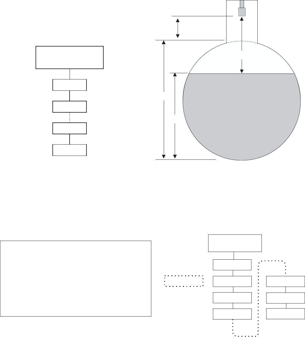
CALIBRATION WORKSHEET - Level Mode
for Horizontal Round Tanks (HRT) and Vertical Tanks
(Ultrason reads) A = ______________
Program Ultrason to show RANGE via:
AquaMetrix
Ultrason
Page 46
CALIBRATION
MODE
RANGE
LINEAR
STORE
RUN
A + B = MAX RANGE
___ + ___ = ___________
A+B-C =MINRANGE
___ + ___ - ___ = ___________
CALIBRATION
MODE
VOLUME
MAX RG
STORE
RUN
LEVEL
HRT
MAX. VOL
MIN RG
Use
for Vertical
Tanks
Program MIN RANGE then
MAX RANGE via:
(DIP STICK) B = ____________
(INSIDE DIA.) C = ____________
MIN RANGE
MUST BE
12 in (305 mm)
OR MORE
C
B
A