
Owner's manual


Table Of Contents
- INDEX
- Bench Test 3
- Connections 3
- Keypad System 4
- Menu - Flow Chart 4
- Run 6
- Totalizer (Flow Mode) 6
- Password 6
- Units / Mode 7
- Flume Selection 9
- Calibration - for Level 10
- Calibration - for Open Channel Flow 11
- 4-20mA Current Loop Offset 12
- Rejection Time 12
- Relay Parameters 13
- Special Functions 15
- Sensor Location - Tank Level 17
- Sensor Mounting/Location - Open Channel 20
- Enclosure Installation 23
- Error/Warning Messages 24
- Field Troubleshooting 25
- Installation Considerations In Noisy Environments 27
- Customer Service 29
- Instrument Return Procedure 29
- Appendix A - Options 30
- Data Logger 32
- RS232C Serial Output 38
- Appendix B - Applications Background 41
- Conversion Guide 42
- Specifications 43
- Calibration Worksheet - Level Mode 46
- Calibration Worksheet - Flow Mode 47
- Units/Mode 1
- Warranty 1
POWER INPUT OPTION
12VDC OR 24VDC
Ultrason Level & Flow Monitors may be ordered factory-configured for 12VDC, or 24VDC power
input.
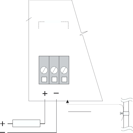
QUICK BENCH TEST:
Connect Sensor as shown below, then Power. When properly connected a soft clicking can be heard
from the sensor and figures will show on the large LCD display. Test operation of the Ultrason by
holding the sensor steadily and aiming at a flat, stable target 12 to 28" (305 to 711 mm) away from the
end of the sensor. Allow a few seconds for the Ultrason to lock onto the target before displaying its
distance. The Ultrason will now display Range in ft or cm (factory calibration).
CONNECTIONS:
POWER INPUT: Connect only 12VDC/0.5 Amps to the + and - terminals for units marked 12V, or
24VDC/0.5 Amps for units marked 24VDC. The Power Input GND must be connected to the nearest
Ground pole. A 1 amp fuse in line is recommended. Power Consumption is 6.5 W continuous.
AquaMetrix
Ultrason
Page 32
GND
12 AWG
MAX
OPTIONAL 24VDC
OPTIONAL 12VDC
POWER INPUT
IMPORTANT:
MUST CONNECT TO A
GOOD GROUND (<1 Ohm)
WITH 12 AWG CONDUCTOR
24VDC
12V or
1 AMP FUSE