
Owner's manual


Table Of Contents
- INDEX
- Bench Test 3
- Connections 3
- Keypad System 4
- Menu - Flow Chart 4
- Run 6
- Totalizer (Flow Mode) 6
- Password 6
- Units / Mode 7
- Flume Selection 9
- Calibration - for Level 10
- Calibration - for Open Channel Flow 11
- 4-20mA Current Loop Offset 12
- Rejection Time 12
- Relay Parameters 13
- Special Functions 15
- Sensor Location - Tank Level 17
- Sensor Mounting/Location - Open Channel 20
- Enclosure Installation 23
- Error/Warning Messages 24
- Field Troubleshooting 25
- Installation Considerations In Noisy Environments 27
- Customer Service 29
- Instrument Return Procedure 29
- Appendix A - Options 30
- Data Logger 32
- RS232C Serial Output 38
- Appendix B - Applications Background 41
- Conversion Guide 42
- Specifications 43
- Calibration Worksheet - Level Mode 46
- Calibration Worksheet - Flow Mode 47
- Units/Mode 1
- Warranty 1
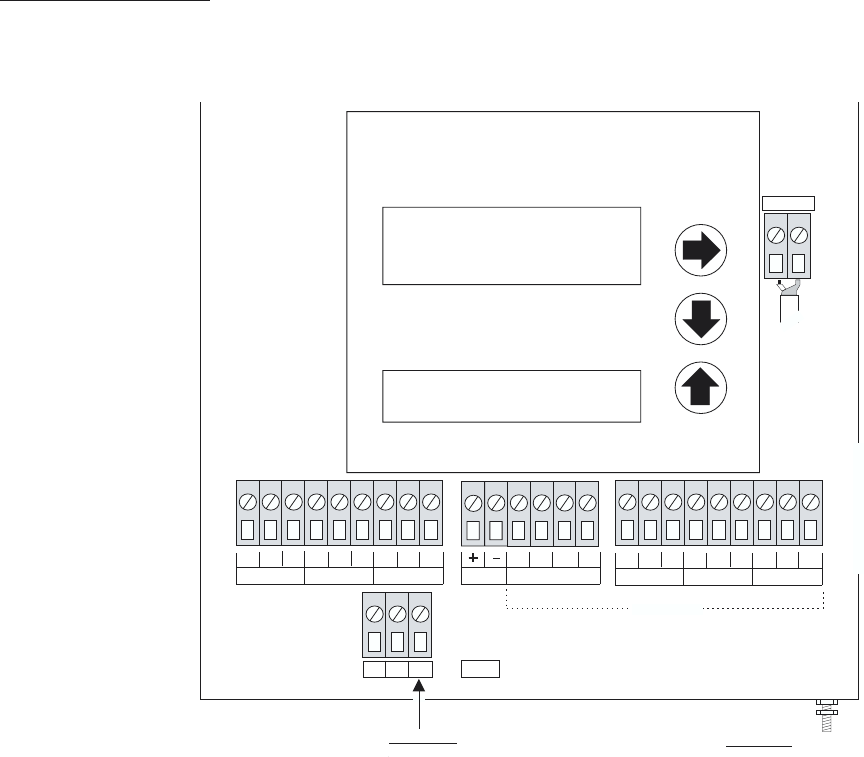
QUICK BENCH TEST:
Connect Sensor to the
T.DUCER terminals as shown below, then apply Power. When properly connected
a soft clicking can be heard from the sensor and figures will show on the large LCD display. Test
operation of the Ultrason by holding the sensor steadily and aiming at a flat, stable target 12 to 28" (305
to 711 mm) away from the end of the sensor. Allow a few seconds for the Ultrason to lock onto the
target before displaying its distance. The Ultrason will now display distance in ft or cm (factory
calibration).
CONNECTIONS:
POWER INPUT: The standard model requires AC power input between 100-130VAC 50/60Hz (2 amp
fuse is recommended). No adjustments are necessary for any voltage in this range. Optional 230VAC
requires power input between 200-260VAC 50/60Hz. (See OPTIONS section of this manual for
connection of optional 12VDC or 24VDC power input).
IMPORTANT NOTE
: To comply with CSA/NRTL standards, AC power input and relay connection
wires must have conduit entry to the instrument enclosure.
AquaMetrix
Ultrason
Page 3
T.DUCER
N.O
C
N.C
N.O
C
N.C
N.O
C
N.C
RELAY 1
RELAY 2
RELAY 3
L
N
G
AC
RX
PU
GND
TX
RS 232
N.O
C
N.C
N.O
C
N.C
N.O
C
N.C
RELAY 4
RELAY 5
RELAY 6
4\20
GROUND STUD
:
ATTACH CABLE
SHIELDS (4-20mA, RS232)
THIS END ONLY
IMPORTANT
IMPORTANT:
MUST CONNECT TO A
GOOD GROUND (<1 Ohm)
WITH 12 AWG CONDUCTOR
OPTIONAL
100-130VAC (50/60 Hz)
OPTIONAL:
200-260VAC (50/60 Hz)
*
*
AMqua etrix
ALUMINUM CHASSIS