
Owner's manual


Table Of Contents
- INDEX
- Bench Test 3
- Connections 3
- Keypad System 4
- Menu - Flow Chart 4
- Run 6
- Totalizer (Flow Mode) 6
- Password 6
- Units / Mode 7
- Flume Selection 9
- Calibration - for Level 10
- Calibration - for Open Channel Flow 11
- 4-20mA Current Loop Offset 12
- Rejection Time 12
- Relay Parameters 13
- Special Functions 15
- Sensor Location - Tank Level 17
- Sensor Mounting/Location - Open Channel 20
- Enclosure Installation 23
- Error/Warning Messages 24
- Field Troubleshooting 25
- Installation Considerations In Noisy Environments 27
- Customer Service 29
- Instrument Return Procedure 29
- Appendix A - Options 30
- Data Logger 32
- RS232C Serial Output 38
- Appendix B - Applications Background 41
- Conversion Guide 42
- Specifications 43
- Calibration Worksheet - Level Mode 46
- Calibration Worksheet - Flow Mode 47
- Units/Mode 1
- Warranty 1
Avoiding noise problems
1. It is recommended that electronic instruments be connected to a relatively clean AC power source.
Use an AC power filter or isolation transformer if necessary.
2. The sensor input line and the control lines (AC or DC) should not be run in the same conduit . The
sensor input should be separated from wires going to inductive loads such as motors, solenoids, relays
and contactors. For best results run the sensor wire in a separate metal conduit. A two-conductor
shielded cable is recommended for the 4-20mA output, the shield should be connected to chassis ground
at the instrument only.
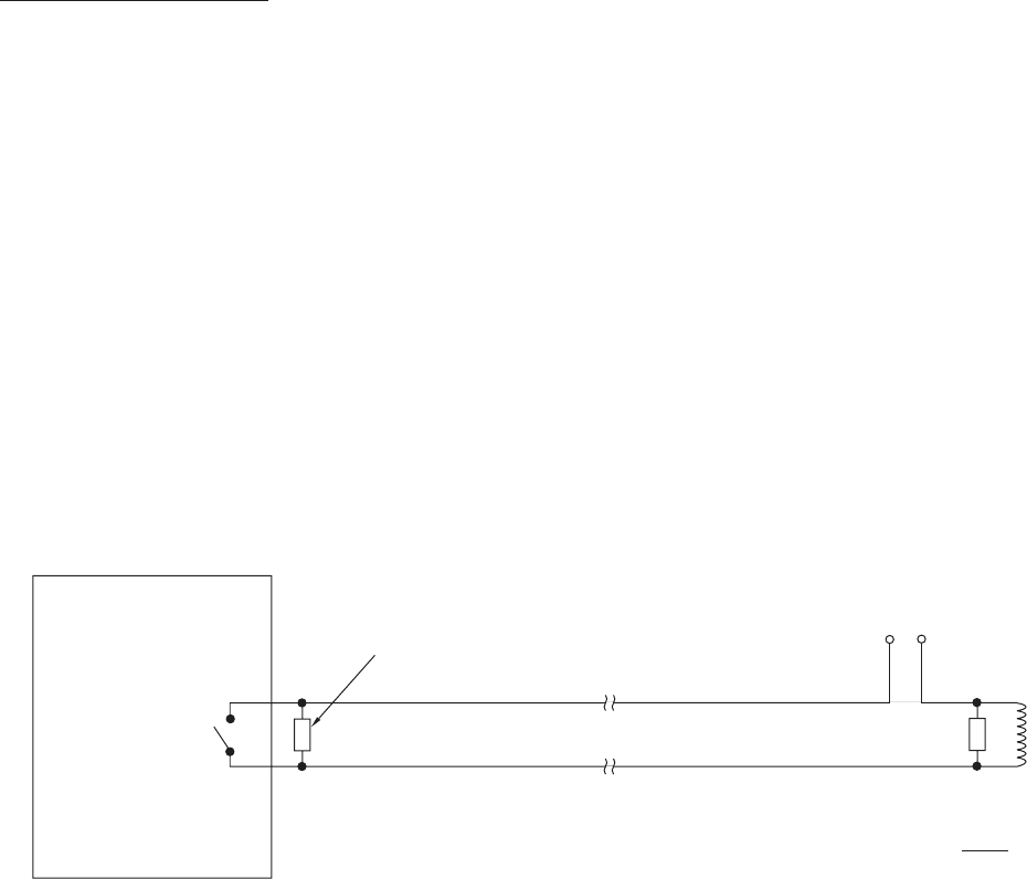
3. For the relay connections, one of most overlooked sources of trouble, noise suppressors are
recommended. Also known as “snubbers” these devices will limit the large spikes produced when the
relay opens, stopping the RFI and also protecting the relay contacts from degrading.
AquaMetrix
Ultrason
Page 28
C
NO
NOISE
SUPPRESSED
AT INSTRUMENT
POWER
240VAC (MAX)
28VDC
NOISE
AT LOAD
(
B
E
S
T)
SNUBBER
LOAD
ULTRASON
N
O
I
S
E
S
UPPRE
SS
I
O
N
O
N RELAY
O
UTPUT
SUPPRESSED
SNUBBER
AQUAMETRIX PART # SNUB