
Owner's manual


Table Of Contents
- INDEX
- Bench Test 3
- Connections 3
- Keypad System 4
- Menu - Flow Chart 4
- Run 6
- Totalizer (Flow Mode) 6
- Password 6
- Units / Mode 7
- Flume Selection 9
- Calibration - for Level 10
- Calibration - for Open Channel Flow 11
- 4-20mA Current Loop Offset 12
- Rejection Time 12
- Relay Parameters 13
- Special Functions 15
- Sensor Location - Tank Level 17
- Sensor Mounting/Location - Open Channel 20
- Enclosure Installation 23
- Error/Warning Messages 24
- Field Troubleshooting 25
- Installation Considerations In Noisy Environments 27
- Customer Service 29
- Instrument Return Procedure 29
- Appendix A - Options 30
- Data Logger 32
- RS232C Serial Output 38
- Appendix B - Applications Background 41
- Conversion Guide 42
- Specifications 43
- Calibration Worksheet - Level Mode 46
- Calibration Worksheet - Flow Mode 47
- Units/Mode 1
- Warranty 1
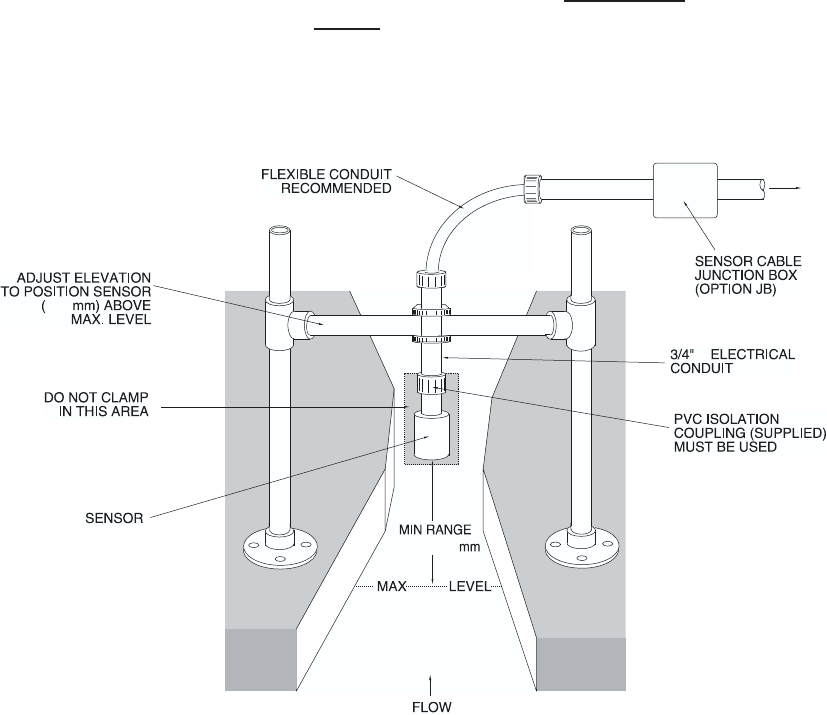
SENSOR MOUNTING/LOCATION
- Open Channel Flow Applications
Each sensor is equipped with a 3/4 inch isolation coupling which MUST be used in your installation. A
threaded nipple or length of conduit may be used to position the sensor at the desired height. The
sensor should be hand-tightened by turning the sensor stem only. DO NOT use a wrench and do not
over tighten.
IMPORTANT: Follow the flume manufacturer’s directions for transducer location. The transducer
should be centered above the flume approach section and mounted ³ 12"/30.5 cm (minimum) above the
maximum liquid level (depending on sensor model).
The transducer should be protected from physical damage and the transducer cable should be routed in
a separate metal conduit.
Because the sensor is equipped with a temperature sensor, it should be shielded from direct sunlight.
Use the PVC “isolation coupling” supplied with the sensor and hand-tighten
the sensor/coupling
assembly onto your mounting stand. Do not
clamp directly to the sensor or to the isolation coupling.
AquaMetrix
Ultrason
Page 20
METAL
CONDUIT
TO ULTRASON
ENCLOSURE
12"
305
12"/305