
Owner's manual


Table Of Contents
- INDEX
- Bench Test 3
- Connections 3
- Keypad System 4
- Menu - Flow Chart 4
- Run 6
- Totalizer (Flow Mode) 6
- Password 6
- Units / Mode 7
- Flume Selection 9
- Calibration - for Level 10
- Calibration - for Open Channel Flow 11
- 4-20mA Current Loop Offset 12
- Rejection Time 12
- Relay Parameters 13
- Special Functions 15
- Sensor Location - Tank Level 17
- Sensor Mounting/Location - Open Channel 20
- Enclosure Installation 23
- Error/Warning Messages 24
- Field Troubleshooting 25
- Installation Considerations In Noisy Environments 27
- Customer Service 29
- Instrument Return Procedure 29
- Appendix A - Options 30
- Data Logger 32
- RS232C Serial Output 38
- Appendix B - Applications Background 41
- Conversion Guide 42
- Specifications 43
- Calibration Worksheet - Level Mode 46
- Calibration Worksheet - Flow Mode 47
- Units/Mode 1
- Warranty 1
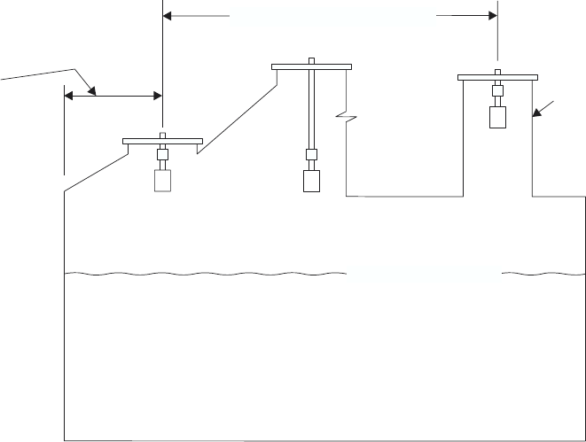
SENSOR MOUNTING LOCATION
- Tank Level/Inventory Applications
SENSOR MOUNTING
Each sensor is equipped with a 3/4 inch “isolation coupling” which MUST be used in your installation.
A threaded nipple or length of conduit may be used to position the sensor at the desired height.
The sensor should be hand-tightened (like a light bulb) by turning the sensor stem only. DO NOT use a
wrench and do not over tighten. DO NOT clamp the sensor below the isolation coupling.
Page 18
AquaMetrix
Ultrason
SENSOR FACE MUST
BE HORIZONTAL ±1°
1 FT (30 cm) HORIZONTAL
FROM SIDEWALL FOR
EVERY 10' (3 m) VERTICAL
NOTE: 2 FT (60 cm) FOR
EVERY 10' (3 m) DEPTH ON
A
PPLICATIONS WITH ROUGH
SIDEWALLS, LADDERS,
REINFORCING RINGS ETC.
MAX. LIQUID LEVEL
PREFERRED SENSOR
LOCATION
6" SCHEDULE 4
0
STAND PIPE IF
EXTENSION
REQUIRED