OPERATING INSTRUCTION MANUAL MODEL 2200R ORP ANALYZER REV. 10 AquaMetrix Inc. 1245 Maple Hill Court, Unit 7 Newmarket, ON Canada, L3Y 9E8 Tel: (800) 742-1413 (905) 954-0841 Fax: (905) 954-0415 www.aquametrix.
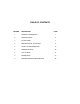
TABLE OF CONTENTS SECTION DESCRIPTION PAGE 1 GENERAL INFORMATION 1 2 SPECIFICATIONS 2 3 INSTALLATION 3 4 DESCRIPTION OF FUNCTIONS 8 5 START-UP AND OPERATION 14 6 OPERATING HINTS 20 7 UTILITY MENU 21 8 DIAGNOSTICS 23 9 TROUBLESHOOTING AND SERVICE 24
MODEL 2200R ORP CONTROLLER INSTRUCTION MANUAL 1.0 GENERAL INFORMATION The AquaMetrix Model 2200R ORP analyzer is a versatile industrial microprocessor based instrument. Setpoints and outputs are programmed through the menu with push buttons on the face of the instrument. Calibration is achieved from the front panel menu. The instrument may be used in conjunction with AquaMetrix 5-wire differential probes or with conventional combination probes.
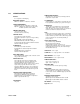
2.0 SPECIFICATIONS DISPLAY: 4 x 7 segment ½” LED Display MEASURING RANGES: ORP: 0 to 1000mV or -1000mV to +1000mV POWER REQUIREMENTS: Standard: 98-132 Vac, 50/60 Hz (less than 5 VA) Optional: 196-264 Vac, 50/60 Hz (less than 5 VA) 23-26Vdc (nominal current 150mA) AMBIENT CONDITIONS: -30 to 50°C (-22 to 122°F) 0 to 90% R.H.
3.0 INSTALLATION 3.1 Location 3.1.1 Install the instrument within 3000 feet of where the AquaMetrix differential probe (R60 Series) is installed. If a conventional combination probe (R500 Series) is used the instrument must be within 25 feet of the probe for direct connection. An AquaMetrix 101 Series preamplifier may be used to extend this distance to 3000 feet. 3.1.
3.4 Electrical Connections The 2200P is available in 3 different power options, 120Vac, 240Vac, and 24Vdc. Refer to following sections for connecting the input power. 120Vac and 240Vac 3.5.1 To access the terminal strips open the door of the instrument and then unscrew the captive retaining screw near the upper right hand corner of the panel. Now swing open the panel to reveal the terminal strip on the power supply circuit board and the smaller terminal strip on the back of the main circuit board.
3.5.2 3.5.3 24Vdc To access the terminal strips open the door of the instrument and then unscrew the captive retaining screw near the upper right hand corner of the panel. Now swing open the panel to reveal the terminal strip on the power supply circuit board and the smaller terminal strip on the back of the main circuit board. The terminal strip on the power supply board at the back of the instrument is labeled for input power, relay outputs and analog outputs.
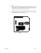
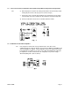
3.5 Sensor Connections 3.5.1 Jumpers J42 are used to select which type of probe is being used. If a differential probe (R60) is used, ensure that both J42 jumpers are in the up position. If a combinational probe is used, ensure that both jumpers are in the down position. (Refer to Fig. 2) 3.5 Probe Connections: DIFFERENTIAL PROBE (R60 SERIES) 3.5.1 Model 2200R Ensure that both J42 jumpers are in the up position, leaving the pins nearest to the bottom exposed.
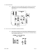
3.6 Sensor Connections; Combination Probe (P500 Series) Without Temperature Compensation 3.6.1 a) Both J42 jumpers located on the swing-out board must be in the down position leaving the pin nearest to the top exposed. (Refer to Fig. 4) c) Connect the active electrode (ring terminal) to the terminal post on the swingout board and connect the shield to the SH terminal of the terminal strip TB2. d) Connect a 300 ohm resistor to the YL and BL terminals on TB2. 3.7 Combination Probe with Preamplifier 3.5.
4.0 Description of Functions 4.1 Overview 4.1.1 The Model 2200R is a microprocessor operated ORP analyzer designed for industrial applications. It is compatible with a wide range of AquaMetrix ORP probes and offers several measurement ranges. The software in the unit makes the instrument very easy to operate and maintain. 4.1.2 The outputs include voltage-free relay contacts and industry standard analog transmission signals. Three programmable relays are provided for process control and alarm.
4.2 Calibration 4.2.1 All ORP systems need to be calibrated when first placed in service and thereafter from time to time. The frequency of calibration can only be found by the operator’s experience with each process. Calibration must always be performed when a new sensor is placed in service. 4.2.2 Calibration is accomplished by using buffer solutions, of known ORP, and adjusting the instrument to show the known ORP value. Buffers are available in 500 mL bottles and in 20 L packs from AquaMetrix.
4.5 Analog Outputs 4.5.1 The analog output signals consists of a non-isolated 0-1 mA, 0-5 Vdc, and isolated 4-20 mA signals. 4.6.3 From the factory all of the analog outputs have a linear range corresponding to the full range of the instrument. The outputs can be scaled to another linear range by entering two values: • Output High: This is the ORP value at which you wish to have 100% output. • Output Low: Model 2200R This is the ORP value at which you wish to have 0% output. 4.5.
4.7 Operation Menu 4.6.1 The operation menu allows the user to recall and to adjust the parameters, required by the analyzer functions. 4.6.2 When the analyzer is powered up, the program will display ORP readings and the STATUS indicator above the display will be green. None of the LEDs in the operation menu will be illuminated. 1.1.1 Five buttons on the panel are used to operate the menu. Use the CALL button to step through the items in the menu.
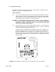
4.7 DIP Switches 3.5.1 The controls which are frequently used in the normal operation of the instrument are all accessible through the operation menu. Some options, which are infrequently used or set only once during installiation, are located on the back of the swing-out board in two banks of dip switches. Both banks (S1 and S2) are located near the upper left corner of the board and consist of 8 switches each. (Refer to Fig.1) 3.5.
4.9 Parameter and Operation Checking 3.5.1 The instrument continuously checks all parameters in its memory, while measuring the ORP. When it detects an invalid value, it flashes the LEDs in the operation menu to indicate the parameter is at fault. You must then access the operation menu to take corrective actions. 4.10 Simulated Input for Testing 4.10.1 TEST is function that can be used to check the setup of the 2200R. When in the test mode the display will show a value between 0mV and 1000mV.
5.0 START-UP AND OPERATION 5.1 Password 5.1.1 To enter the menu press CALL and the PASSWORD LED will illuminate. If the password feature has been disabled by the dip switch, TEST will be the first menu item illuminated when the CALL button is pressed. With each press of CALL button you will step through the menu. When the last item, ALARM LOW is reached the menu wraps around to TEST. If you have enabled PASSWORD by placing DIP Switch No.
5.4 Analog Output Range Expand 3.5.1 To increase the resolution of the analog outputs, the range may spread over any section of the scale. as long as is spans at least 10% of full scale. The best way to describe this setup is by example. Suppose you wish the outputs to span from 200mV to 600mV. Proceed as follows: a) Enter the menu by pressing CALL until the OUTPUT HIGH LED is illuminated. Use the arrows keys to make the display read 600. Press ENTER.
a) Enter the menu by pressing CALL, proceed by pressing CALL until the RELAY A DEADBAND LED is illuminated. Now use the arrow keys to make the display read the desired value. Press ENTER. The display will flash until ENTER is pressed again to confirm the value. b) Press RUN, to place the instrument on line, or press CALL for another menu selection. 5.7 Control Relay B Setpoint / Deadband 3.5.1 Control Relay B is configured the same as Relay A. (Refer to Sec. 5.5 / 5.
5.10 Cycle Feature for Relays A and B 3.5.1 The 2200R has a cycling feature for the control relays. This feature if enabled will cause the relays to cycle based on the on and off times selected. This useful feature can help eliminate overshooting, saving expensive chemicals. c) If you wish to have cycling control for Relay A, you must put DIP switch NO. 3 of Bank S2 in “ON” position. Similarly, if you wish to have cycling control for Relay B, put DIP switch No. 4 of Bank S2 in “ON” position (See Section 4.
5.12 Alarm Low 5.12.1 To set the ALARM LOW proceed as follows: a) Press CALL to enter the menu, proceed by pressing CALL until the ALARM LOW LED is illuminated. With the arrows make the display read the desired value. Press ENTER. The display will flash until ENTER is pressed again to confirm entry. b) Press RUN to place the instrument on line, or press CALL, for another menu selection.
5.15 Status 3.5.1 The 2200R continuously checks the integrity of all stored data and monitors the condition of the measuring system. If a fault is detected, the STATUS LED above the display will change from green to red. When this occurs, enter the menu and scroll through the menu until the STATUS LED illuminates. The display will show a numerical code to assist you, in correcting the problem.
6.0 OPERATING HINTS 6.1 Probe Care 6.1.1 Keep the probe clean using the procedure recommended in the probe manual. Although the differential probe will continue to operate when fouled, excessive fouling may cause incorrect readings or very slow response. 3.5.1 Be sure the probe cable is well protected. The probe cable should be run in conduit but never in the same conduit with line power. Sufficient excess cable should be allowed for removal of the probe for cleaning and calibrating. 3.5.
7.0 UTILITY MENU 7.1 Utility Menu Functions 3.5.1 The Utility Menu enables authorized personnel to perform the following: • Calibrate the range of the instrument • Fine tuning the 0-1 mA/ 0-5 Vdc output • Fine tuning the 4-20 mA output 7.2 Access to Utility Menu 7.2.1 The Utility Menu is protected by password. To access the Utility Menu press and hold both RUN and ENTER for five seconds until the PASSWORD LED illuminates. The green STATUS light will flash.
7.4 Adjust 0-1 mA / 0-5 Vdc Output 7.6.1 It may be desirable to fine tune the 0-1 mA / 0-5 Vdc output to take into account the characteristics of your particular loop. The following method involves a high and low calibration and requires the use of a digital multi-meter. (DMM). Proceed as follows ignoring the instrument display: a) Turn off the power to the instrument. Connect your DMM to the 0-5 Vdc output terminals on the power supply board. b) Turn on the power. Enter the Utility Menu as described in 7.
8.0 DIAGNOSTICS 8.1 Description 8.1.1 The 2200R has diagnostic features which alerts the operator to invalid entries and memory loss. Invalid entries are indicated by the flashing of the appropriate menu LED. The flashing will commence after RUN is pressed and will continue until the errors are corrected. Memory loss is indicated by the flashing of TEST and by the alarm relay if enabled by DIP Switch No. 5 of Bank S1. Refer to Section 4.7.3. 8.2 Invalid Calibration 3.5.
9.0 TROUBLESHOOTING AND SERVICE 9.1 Calibration / Display Problem 3.5.1 If the problem is one of inability to calibrate or the display does not appear to match the input, try the RESET feature. See Section 6.4. In rare cases, the ESCAPE feature might be used. Refer to Section 9.3. 9.2 Isolate the cause 9.2.1 When a measurement problem occurs, the first step is to try to isolate the cause. If the 2200R is powered, go through the menu and check your settings. A convenient way to do this is to call TEST.
b) To check the temperature channel move the slide switch S41 from position “ON LINE” to position TEST. Go to the TEMPERATURE Menu item. The display should be 25.0°C ± 0.1°C, in which case the analyzer is in order and the problem is in the sensor. Otherwise the problem is in the analyzer. For normal operation both slide switches S40 and S41 must be in “ON LINE” position. 9.3 “Escape” Procedure 9.3.
• The cycling parameters if so equipped – See Section 5.14 h) After all the above operations are performed the STATUS will turn green and status 0 should be obtained. i) Bring the unit on-line for measurement and control by pressing RUN. j) The unit may be tested now, using the TEST menu item (see Section 5.12), or the built-in self-testing feature (see Section 9.2.5). 9.4 Printed Circuit Board Replacement 9.4.
9.7 Parts and Accessories 9.7.1 The major parts are listed below. When ordering parts please use the complete part number. Description 500 mL 200mV ORP Buffer Solution 500 mL 600mV ORP Buffer Solution Fuse, 0.25A Quantity of 5 2200 Power Supply Circuit Board Assembly 120Vac 2200 Power Supply Circuit Board Assembly 240 Vac 2200R Microprocessor Circuit Board Assembly (includes front panel and hinge) Part # A35-40 A35-41 A35-72 C13-103A C13-103B C13-2200R 9.8 Instrument Return 9.8.
STATEMENTS OF CONFORMITY FROM THE MANUFACTURER U.S.A. Canada WARNING: This equipment generates, uses, and can radiate radio frequency energy and if not installed and used in accordance with the instructions manual, may cause interference to radio communications.