OPERATING INSTRUCTION MANUAL MODEL 2200D/P91 DISSOLVED OXYGEN SYSTEM REV. 7.0 AquaMetrix Inc. 22-121 Granton Drive Richmond Hill, ON Canada, L4B 3N4 Tel: (800) 742-1413 (905) 763-8432 Fax: (905) 763-9480 www.aquametrix.
TABLE OF CONTENTS GENERAL INFORMATION 1 SPECIFICATIONS 2 INSTALLATION 4 DESCRIPTION OF FUNCTIONS 8 START-UP AND OPERATION 12 OPERATING HINTS 16 UTILITY MENU 17 DIAGNOSTICS 20 TROUBLESHOOTING AND SERVICE 21
MODEL 2200D DISSOLVED OXYGEN ANALYZERS AND MODEL P91 DISSOLVED OXYGEN SENSOR INSTRUCTION MANUAL 1.0 GENERAL INFORMATION The AquaMetrix Model 2200D Dissolved oxygen analyzer is a versatile industrial microprocessor based instrument. Outputs are programmed through the menu with push buttons on the face of the instrument. Calibration is also accomplished through the front panel menu. The instrument must be used in conjunction with the AquaMetrix Model P91 dissolved oxygen sensor.
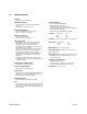
2.0 SPECIFICATIONS DISPLAY: 3 1/2 digit LED, 1/2" high digits MEASURING RANGES: D.O.: 0-20.00 ppm and 0-100% saturation, switch selectable Temperature: 0-40°C (32 to 104°F) POWER REQUIREMENTS: 98-132 Vac, 50/60 Hz (less than 10 VA) Optional: 196-264 Vac, 50/60 Hz AMBIENT CONDITIONS: -30 to 50°C (-22 to 122°F) 0 to 90% R.H.
MODEL 2200D-X-2-X ADDITIONAL FEATURES CONTROL RELAYS: Two relays can be independently set for operation in response to rising or falling value and for fail-safe operation. Deadband (hysteresis) independently adjustable. Rating: 5A 115/230 Vac, 5A 30 Vdc. SPDT ALARM RELAY: High-Low with fixed deadband of 2% of full scale. Normal or fail-safe operation. Rating: 5A 115/230 Vac, 5A 30 Vdc.
3.0 INSTALLATION 3.1 Location 3.1.1 Locate the instrument within the reach of the cable provided for the P91 sensor. 3.1.2 Select an installation site which is: • free of mechanical vibrations • reasonably clean and dry • protected from falling corrosive fluids within the ambient temperature and humidity specifications • remote from high voltage relay and power switches 3.2 Type of Mounting 3.2.1 If the instrument is to be pipe or panel mounted a special hardware kit will be required.
3.5 Sensor Installation, Flotation Mounting 3.5.
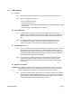
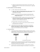
d) The sensor may be attached to float assembly in one of two ways: 1. With sensor EXTENDED FROM BOTTOM of flotation ball: Insert 12-inch long extender pipe into the flotation ball and fasten it to the end of adapter pipe. This will extend the sensor’s membrane 12 inches below the flotation ball. NOTE: Extender pipe supplied only when ordered. 2. With the sensor membrane FLUSH WITH BOTTOM of flotation ball: Disregard using extender pipe and proceed with Step e).
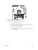
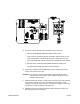
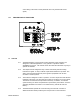
h) Install pivot mounting bracket and mount junction box on the bracket. Insert pipe/sensor assembly through the bracket to the desired position. Tighten pipe locking screw. 3.6 Sensor Installation, Submersion Mounting 3.6.1 a) Refer to diagram below and proceed as follows: b) Route sensor cable through pipe and fasten sensor to pipe. The use of thread sealant (Teflon tape) on all mounting hardware and sensor threads is recommended to avoid leaks.
control wiring in the same conduit (“electrical noise” may interfere with sensor signal). 4.0 DESCRIPTION OF FUNCTIONS 4.1 Overview 4.1.1 The Model 2200D is a microprocessor based dissolved oxygen analyzers are designed for industrial applications. They operate in conjunction with the AquaMetrix P91 sensor. The software in the unit makes the instrument very easy to operate and maintain. 4.1.2 The outputs include voltage-free relay contacts and industry standard analog transmission signals.
Some of these are: • • • • • • • • Recall and easy adjustment of relay and output parameters Push button calibration A HOLD function for outputs Continuous sensor check during measurement Continuous self check and watch-dog timer to ensure correct operation Password protection of stored values Temperature Output Simulated input for testing 4.2 Calibration 4.2.1 The 2200D is calibrated at the factory, with the sensor purchased with the instrument.
4.6 Analog Outputs 4.6.1 The analog output signals consist of a non-isolated 0-1 mA, 0-5 Vdc, and isolated 420 mA signals. 4.6.2 From the factory all of the analog outputs have a linear range corresponding to the full range of the instrument. The 4-20 mA output can be programmed to another linear range by entering two values: • Output High: This is the D.O. value at which you wish to have 100% output. • Output Low: This is the D.O. value at which you wish to have 0% output. 4.6.
• Output High • Output Low In addition, Model 2200D-X-2 has the following items: • • • • • • Relay A Setpoint Relay A Deadband Relay B Setpoint Relay B Deadband Alarm Relay High Alarm Relay Low 4.8 DIP Switches 4.8.1 The controls which are frequently used in the normal operation of the instrument are all accessible on the control panel. Some switches, which are infrequently used are located on the back of the swing-out board. 4.8.
4.9 Output Hold 4.9.1 Output hold, is a function which freezes all output signals at the last value to prevent the occurrence of wild distortions during programming and maintenance. 4.9.2 When the Operation Menu is entered by pressing CALL, the alarm relays and the analog outputs are automatically placed on hold and remain on hold until the instrument returns to on line. The output hold will remain for a maximum of 10 minutes after the last button was pressed, if this feature has been enabled.
5.2 Percent Saturation/ppm 5.2.1 The instrument provides measurement of dissolved oxygen in either percent saturation or ppm. In ppm measurement the reading is automatically compensated for temperature changes in the medium. a) To select units of measurement enter the menu by pressing CALL to indicate %sat/ppm. b) Press the UP arrow button to select %sat or the DOWN arrow button or select ppm. c) Press RUN to return to on line or press CALL for another menu selection. 5.3 Calibration 5.3.
5.4 Analog Output Range Expand 5.4.1 The 4-20 mA isolated analog output may be spread over any section of the scale as long as that section is at least 10% of full scale. The best way to describe this setup is by example. Suppose you wish the 4-20mA output to span 4 ppm to 10 ppm. Proceed as follows: a) Press CALL as many times as required until OUTPUT HIGH is indicated. Now use the arrows to make the meter read 10 ppm. Press ENTER. The display will flash until ENTER is pressed again to confirm entry.
5.7 Status 5.7.1 The 2200D continuously checks the integrity of all stored data and monitors the condition of the measuring system. If a fault is detected, the FAIL LED above the display will turn red. The STATUS in the operation menu will provide a numerical code, giving a possible cause and a suggested remedy. 5.7.
c) Press CALL the required number of times until RELAY A SETPOINT is indicated. Now use the arrows to make the display read the desired value. Press ENTER. The display will flash until ENTER is pressed again to confirm entry. A LED above the display indicates when Relay A is activated. d) Press RUN to place the instrument on line or press CALL for another menu selection. 5.9 Relay A Deadband (For Model 2200D-X-2 only) 5.9.
The display will flash until ENTER is pressed again to confirm the entry. b) Press RUN to place the instrument on line, or press CALL, for another menu selection. 5.13 Alarm Low (For Model 2200D-X-2 only) 5.13.1 a) Press CALL until ALARM LOW is indicated. With the arrows make the meter read the desired value. Press ENTER. The display will flash until ENTER is pressed a second time to confirm entry. b) Press RUN to place the instrument on line, or press CALL, for another menu selection.
6.4 Output Hold 6.4.1 It may be useful during some system maintenance procedures to place the relay and analog outputs on hold. To accomplish this simply press CALL. To return to on line operation press RUN. NOTE: To safeguard against the operator forgetting to press RUN the instrument will automatically go back on line ten minutes after the last button was pressed provided this feature has been enabled by placing DIP switch No.7, Bank S1, in the ON position. 7.0 UTILITY MENU 7.
a) Enter the Utility Menu as described in 7.2.1. b) Press CALL to indicate OUTPUT HIGH, which is the “Temperature output, 100% point” in the Utility Menu. (See table in 7.2.2). Now use the arrow button to show 45.0 on the display. Press ENTER. The display will flash until ENTER is pressed again to confirm entry. c) Press CALL to indicate OUTPUT LOW, which is the “Temperature output, 0%, point” in the Utility Menu. (See table in 7.2.2). Now use the arrow buttons to show 10.0 on the display.
c) Press CALL to indicate CALIBRATION, which is "4-20 mA Output adjust, low" in the Utility Menu (See table in 7.2.2.) Now use the arrow keys to make your DVM read 8 mA. Press ENTER twice to confirm. d) Press CALL to indicate TEMPERATURE, which is "4-20 mA Output adjust, high" in the Utility Menu (See table in 7.2.2). Now use the arrow keys to make your DVM read 16 mA. Press ENTER twice to confirm. e) Press RUN to return to on line or press CALL to proceed to another item in the Utility Menu. 7.
9.0 TROUBLESHOOTING AND SERVICE 9.1 Isolate the cause 9.1.1 When a measurement problem occurs, the first step is to try to isolate the cause. If the 2200D is powered, go through the menu and check your settings. A convenient way to do this is to call TEST. See Section 5.5. 9.1.2 If your 2200D appears dead or intermittent, check the breaker, make sure that the instrument is set up for the available line voltage and make sure the line voltage is actually available at the terminals.
e) Now proceed to turn each of the other S43 switches On with the remaining switches Off. The display should read within 5% of 25°C with Switch 2 On and 35°C with Switch 3 On. If this is the case the analyzer is in order and the problem is in the sensor. Otherwise the problem is in the analyzer. f) Return S40 and S41 to “On line” and ensure that all S43 switches are Off. 9.2 Escape 9.2.
• Output High and Low - See Section 5.4. (For Model 2200D-X-2) • Control Relay - See Sections 5.8 and 5.9. • Alarm Relay - See Sections 5.12 and 5.13. d) After all the above operations are performed the FAIL LED will turn off (For Model 2200D-X-1) and STATUS LED will turn green (For Model 2200D-X-2) and Status “0” should be obtained. e) The unit may be tested now, using the TEST menu item (See Section 5.5), or the built-in self-testing feature, (See Section 9.1.
9.6 Customer Service 9.6.1 If a problem has not been resolved with the above procedures, a telephone consultation with your AquaMetrix representative, or directly with AquaMetrix will provide the answer. AquaMetrix Inc. 22-121 Granton Drive Richmond Hill, Ontario L4B 3N4 Canada Tel: (800) 742-1413 (905) 763-8432 Fax: (905) 763-9480 Email: support@aquametrix.com 9.7 Parts and Accessories 9.7.1 The major parts are listed below. When ordering parts please use the complete part number.
STATEMENTS OF CONFORMITY FROM THE MANUFACTURER U.S.A. Canada WARNING: This equipment generates, uses, and can radiate radio frequency energy and if not installed and used in accordance with the instructions manual, may cause interference to radio communications.