
User's Manual

PRELIMINARY
FCC ID: BIB61201001
INTALLATION 3-18
PRELIMINARY
MCC-6120 SDR Packet Data Radio Network
3.4 Operational Test Procedure
3.4.1 RF Test
A very thorough RF test can be made by entering the command TEST [ENTER]. TEST causes
the processor to turn the transmitter ON and measures the forward and reverse RF power that is
being transmitted. It also measures the battery voltage under load and the antenna noise voltage.
The following response will be displayed on the operator terminal:
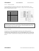
syncs xmits acks pwr-fwd pwr-rev v-bat det-rf resets
xxxx yyyy zzzz aaaa bbbb ccc ddd eee
where: xxxx = # of sync patterns received from the master station.
yyyy = # of transmissions made by the MCC-6120 SDR.
zzzz = # of acknowledgements received from the Master Station.
aaaa = Forward power in watts. This should be greater than 80 watts.
bbbb = Reflected power in watts. This should be less than 5 watts.
ccc = Battery voltage under load (while transmitting). This should be greater
than 10.6 V
DC
.
ddd = Received signal strength in dBm. This will normally be the noise level
at the antenna and should read about –120.
eee = Number of times the radio has rebooted.
NOTE
The forward RF power should be at least 80 watts when operating at Low Band VHF, and 25
watts when operating in High Band VHF if the battery voltage is normal. If it is lower than these
values check for proper cabling to the power source (see Section 3.2.2.1.).
If the reverse RF power is greater than 5 watts on any channel check the antenna and coaxial
cabling for proper installation.
If both the forward and reverse power are low, the transmitter may be automatically shutting
down due to an antenna VSWR greater than 3:1. Check the antenna and coaxial cabling for
proper installation.
The DET RF value indicates the level of the RF signal plus noise at the antenna in dBM (dB
above or below 1 milliwatt of power). Use the mm,50,dist command to obtain just the noise
value. This noise level should be less than -90 dBM. The lower the number the lower the noise
and the larger the operating range of the unit will be. Refer to Section 3.1 for reducing site noise
conditions.
An overall figure of merit for the link performance is the XMIT to ACK ratio. If this ratio is 3:1
or lower, the overall performance will be very good.
This completes the initialization and power-up sequence of the MCC-6120 SDR.
The unit is now ready for operation.