
User's Manual

PRELIMINARY
FCC ID: BIB61201001
INTALLATION 3-3
PRELIMINARY
MCC-6120 SDR Packet Data Radio Network
The power cable between the battery and the MCC-6120 SDR should be kept shorter than 10 feet
and rated at #14 AWG or lower. (See Section 3.2.2.1 for more details.)
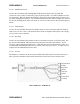
3.1.3 Antenna Selection
Vertical polarization is used in a network to provide omni-directional coverage to all adjacent
nodes in the LOS network. A good choice for a base station antenna is dual stacked dipoles
mounted on two sides of a triangular tower. A ½ wavelength whip is a good antenna choice for a
data collection site.
For mobile applications, a ¼ wavelength dipole is a good choice when mounting to a roof for
fender of a vehicle.
IMPORTANT
Refer to the Important Safety Instructions for Installers and Users at the front of this manual
for RF Exposure Information. This section contains a list of precautions that must be observed
in order to comply with Federal Communications Commission safety standards for human
exposure to radio frequency (RF) energy.
The information bandwidth of the system is less than 25 kHz, therefore, a very narrow
bandwidth antenna may be used. The antenna must provide a 50Ω load.
Always consult with MCC’s engineering department for assistance when any questions arise
with respect to antenna selection.
Assembly instructions are included with each antenna. Please refer to these for proper assembly
for all antenna elements.
3.1.4 Antenna Height
In general, the higher the antenna is above ground the better the performance will be. The link
gain will be increased by approximately 6 db every time the antenna height is doubled. A trade-
off will be the antenna cable length because this must be kept as short as possible to minimize
line losses. Line loss between the antenna and the MCC-6120 SDR should be less than 2 db.
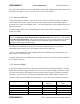
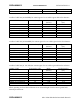
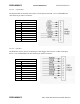
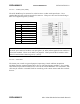
A table of cable loss (at 50 MHz) for various types of co-ax cable is given below for reference.
CABLE TYPE Loss/100 feet (db) Diam.
(Inches)
Weight/100 feet
(lbs.)
RG 223, RG 58 3.0 .211 3.4
RG 214, RG 8 1.8 .425 12.6
RG 17 1.2 .870 20.1
LMR-240 ultra flex 2.0 .240 3.4
LMR-400 ultra flex 1.0 .405 9.0