
Operating Manual


PRELIMINARY
FCC ID: BIB61201001
INTALLATION 3-13
PRELIMINARY
MCC-6120 SDR Packet Data Radio Network
3.3 Power-Up Sequence
IMPORTANT
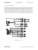
Before applying power to the MCC-6120 SDR, check all connections between the MCC-6120
SDR and the external equipment (power, antenna, operator terminal, and data logger). Refer to
Section 3.2.3 for cabling instructions.
3.3.1 Connect Operator Terminal
Connect a laptop or an operator terminal, with XTERMW installed and running, to the Operator
Port. XTERMW is an MCC windows-based terminal emulation program designed for
interfacing with MCC products. The operator terminal must be programmed with the same
configuration parameters as the Operator Port.
The Operator Port of the MCC-6120 SDR is programmed with the following factory default
configuration at the time of shipment:
Baud rate 9600 Parity none
Data bits 8 Protocol ASCII
Stop bit 1 Flow control none
3.3.2 Power Connection
Power up the MCC-6120 SDR by applying +12VDC to the power connector.
NOTE
When the unit transmits, it will draw up to 20 amps; therefore, review section 3.2.3.1 for proper
cabling to the power source. The voltage drop at the input connector during transmission should
be less than 2 V
DC
for proper operation of the unit. Verify this during the Operational Test
Procedure in Section 3.4.
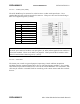
When power is initially applied to the MCC-6120 SDR, or after a software boot or hardware
reset, the following message will be displayed:
MCC-6120 SDR PACKET DATA RADIO
(c) Copyright 2005 Meteor Communications Corp.
All Rights Reserved
S/W Part Number P1101-00-00 MCC-6120 Version 1.14 11/05/05
S/W Part Number P1102-00-00 DSP SDR Version 1.10 07/14/04
S/W Part Number P1103-00-00 DSP FPGA Version 4 07/14/04
S/W Part Number P1121-00-00 Flexbus FPGA Version 7 11/03/05
* Part Number, Version Number, and date vary according to a particular radio’s Firmware.