
Operating Manual

PRELIMINARY
FCC ID: BIB61201001
INTALLATION 3-10
PRELIMINARY
MCC-6120 SDR Packet Data Radio Network
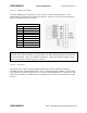
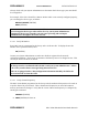
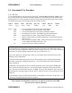
SENSOR PORT
Pin Signal
1 Optocoupled input #1 positive
2 (no connection)
3 Optocoupled input #2 positive
4 Optocoupled input return
5 Optocoupled input #3 positive
6 (no connection)
7 Optocoupled input #4 positive
8 (no connection)
9 Ground
10 MIC_HI
11 MIC_LO
12 Push-To-Talk
13 RX_AUDIO1
14 RX_AUDIO2
15 MUTE
16 Switched +12V (0.5A maximum)
17
Analog Input #1 ( 0 to 5 V) ±0.5%
18
Analog Input #2 ( 0 to 5 V) ±0.5%
19
Analog Input #3 ( 0 to 5 V) ±0.5%
20
Analog Input #4 ( 0 to 5 V) ±0.5%
21
Analog Input #5 ( 0 to 5 V) ±0.5%
22
Analog Input #6 ( 0 to 5 V) ±0.5%
23 +5V Reference
(10mA for sensor excitation)
24 +12V (0.5A maximum)
25 Detected RF Test Point
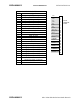
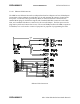
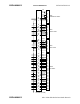
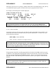
1
2
3
4
5
6
7
8
9
10
11
12
13
14
15
16
17
18
19
20
21
22
23
24
25
IN1+
NC
IN2+
IN–
IN3+
NC
IN4+
NC
GND
MIC_HI
MIC_LO
PTT
RX_ AUDIO 1
RX_ AUDIO 2
MUTE
+12Vsw
ADC1
ADC2
ADC3
ADC4
ADC5
ADC6
+5VREF
+12V
DETRF
D25S
SENSOR
PORT