
Operating Manual

PRELIMINARY
FCC ID: BIB61201001
INTALLATION 3-9
PRELIMINARY
MCC-6120 SDR Packet Data Radio Network
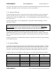
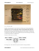
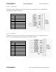
3.2.2.5.3 Auxiliary Port (AUX)
The AUX PORT may be connected to a GPS receiver or other serial input device. Use a
standard RS-232 cable with a 9-pin male D connector. This port is also used for interfacing to
MCC test equipment (pins 6, 8, and 9).
AUX PORT – 9S
Pin Signal
1 Not Used
2 Tx Data
3 Rx Data
4 Not Used
5 Ground
6 MCLK (TTL)
7 Not Used
8 MDIR (TTL)
9 MSET (TTL)
IMPORTANT
The AUX port connector has three extra pins (pins 6, 8, and 9) whose signals do not conform to
the RS-232 standard. These are for MCC test purposes. These pins will NOT interfere with a
normal 3-wire RS-232 connector (pins 2, 3, and 5).
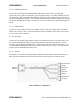
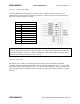
3.2.2.5.4 Sensor Port
The Sensor port is used as a general purpose Supervisory Control and Data Acquisition
(SCADA) interface requiring limited I/O in lieu of a full data logging capability. Use a mating
cable with a 25-pin male D connector for access to the various functions. For convenience, this
cable may be routed to a terminal block for interfacing to the various sensors and other external
devices.