
Operating Manual

PRELIMINARY
FCC ID: BIB61201001
INTALLATION 3-7
PRELIMINARY
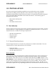
MCC-6120 SDR Packet Data Radio Network
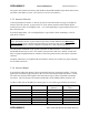
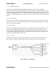
I/O Port
(44 Pin)
Operator Port
(9 Pin)
Aux Port
(9 Pin)
Data Port
(9 Pin)
Sensor Port
(25 Pin)
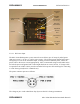
3.2.2.2 LB/HB Connectors
Connect the Low Band VHF and High Band VHF antenna cables to the two BNC RF
connectors, being careful to observe the proper frequency bands. Use double-shielded coax for
all connections. RG-223 (double-shielded) may be used for cable lengths under 30 feet for the
low band and high band antenna. Use a double-shielded cable RG-214 for lengths up to 100 feet
for the low and high bands. Refer to Section 3.1.4 for coax cable losses at the various frequency
bands.
3.2.2.3 GPS Antenna
Connect an external GPS antenna to this SMA connector on the front panel when the internal
GPS receiver is used. Note: GPS antennas have a built in amplifiers that require a DC voltage
(3-5 V) on the center conductor.
3.2.2.4 802.11(b)
Connect an external 802.11(b) antenna to this reverse-SMA connector on the front panel. Use
the Antenex TRA24003P 3dB omni directional antenna for the 802.11(b) antenna. Avoid
excessive cable lengths that would induce >3 dB cable loss from the antenna to the radio. It is
recommended that LMR 240 Ultra Flex be used for cable runs up to 20 feet. If longer runs are
required, use the LMR 400 Ultra Flex cable.
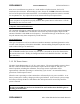
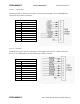
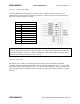
3.2.2.5 I/O Port
The 44 pin I/O connector on the front panel includes three RS-232 ports and one Sensor port.
MCC provides a standard cable harness that breaks out these four ports as shown below:
MCC PART NO. 14001352-01