
Operating Manual


PRELIMINARY
FCC ID: BIB61201001
DESCRIPTION 2-9
PRELIMINARY
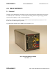
MCC-6120 SDR Packet Data Radio Network
2.3 SDR Modules
The MCC-6120 SDR contains four printed circuit board assemblies as shown in Figure 2.3-1.
• A 32-bit Communications Management Unit (CMU) microprocessor controller performs
the radio control, link and network protocol functions. This assembly also contains a
digital signal processor (DSP) and a digital-to-analog converter (DAC) for generating the
GMSK RF signal. The DSP also receives and demodulates the receive GMSK signals on
all bands.
• A 30W, 3-stage power amplifier, filters, and mixers for operation in the 151-162 MHz
band
• A 100W, 3-stage power amplifier in the 39-50 MHz band.
• A 12-channel GPS receiver that can be mounted on the processor board as an optional
subassembly.
• An 802.11(b) Module (15mW) mounted on the CMU board.
All components are soldered in place using surface mount technology. As an option, the boards
can be conformal coated with an acrylic encapsulate that contains a tropicalizing, anti-fungal
agent to provide additional protection against moisture and contamination.
2.4 Detailed Specifications
The detailed specifications for each of the printed circuit board assemblies are given in Tables
2.1 through 2.6.
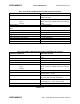
MCC-6120 SDR GENERAL SPECIFICATIONS
CHARACTERISTIC SPECIFICATION
Dimensions 10.6”L X 4.0”W X 4.4”H
Weight 6.0 lbs.
Temperature Range
-30° to 60° C (-22° to 140° F)
Power Requirements 12 V
DC
Nominal (10-15 V
DC
)
Standby: 600 mA (Continuous)
Transmit: 22 Amps Nominal (Low Band)
8 Amps Nominal (High Band)
TABLE 2.1