
User's Manual

545C Operations Manual
02/10/2012 Prerelease DCN 00001789-A
80 © 2012 Meteorcomm LLC. All Rights Reserved. Proprietary and Confidential. Do Not Distribute.
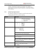
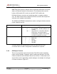
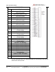
SENSOR PORT
Pin Signal
1
Optocoupled input #1 positive
(500 ohm resistor)
2
Optocoupled input #1 return
3
Optocoupled
input #2 positive
(500 ohm resistor)
4
Optocoupled input #2 return
5
Optocoupled input #3 positive
(500 ohm resistor)
6
Optocoupled input #3 return
7
Optocoupled input #4 positive
(500 ohm resistor)
8
Optocoupled input #4 return
9
Ground
10
Relay Output #1 Normally Open
(2 Amp rating)
11
Relay Output #1 Common
12
Relay Output #1 Normally Closed
(2 Amp rating)
13
Relay Output #2 Normally Open
(2 Amp rating)
14
Relay Output #2 Common
15
Relay Output #2 Normally Closed
(2 Amp rating)
16
Switched +12V (battery)
17
Analog Input #1 ( 0 to 5 V)
18
Analog Input #2 ( 0 to 5 V)
19
Analog Input #3 ( 0 to 5 V)
20
Analog Input #4 ( 0 to 5 V)
21
Analog Input #5 ( 0 to 5 V)
22
Analog Input #6 ( 0 to 5 V)
23
+5V Reference
(10mA for sensor excitation)
24
+12V (0.5A maximum)
25
Detected RF Test Point
A 25-pin terminal block is a convenient means for interfacing to the various
sensors and control points.