
User's Manual

545C Operations Manual
02/10/2012
40
© 2012 Meteorcomm LLC.
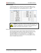
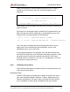
The following response will be displayed on the operator terminal:
syncs xmits acks pwr
xxxx yyyy zzzz aaaa bbbb ccc ddd eee
where: xxxx =
# of sync patterns received from the master station.
yyyy =
# of transmissions made by the MCC
zzzz =
# of acknowledgements received from the Master
aaaa =
Forward power in watts
bbbb =
Reflected power in watts
ccc =
Battery voltage under load (while transmitting)
greater than 10.6
ddd =
Received signal strength in
noise level at the antenna and should read about
eee =
Number of times the radio has rebooted.
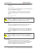
Note:
The forward RF power should be at least 80 watts if the battery
voltage
is normal. If it is lower than 80 watts check for proper cabling to
the power source. (See Section 3.2.2.1.)
If the reverse RF power is greater than 5 watts check the antenna and
coaxial cabling for proper installation.
If both the forward and reverse pow
automatically shutting down due to an antenna VSWR greater than 3:1.
Check the antenna and coaxial cabling for proper installation.
If the DET RF is greater than
will still perfo
rm properly but the latency time of the link will be increased.
Refer to Section 3.1 for reducing site noise conditions.
An overall figure of merit for the link performance is the XMIT to ACK ratio.
If this ratio is 3:1 or lower, the overall performance wi
This completes the initialization and power
The unit is now ready for operation.
Refer to Chapter 4 for detailed operating instructions.
Prerelease
DCN
.
All Rights Reserved. Proprietary and Confidential. Do
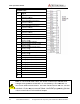
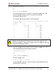
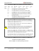
The following response will be displayed on the operator terminal:
syncs xmits acks pwr
-fwd pwr-rev v-bat det-
rf resets
xxxx yyyy zzzz aaaa bbbb ccc ddd eee
# of sync patterns received from the master station.
# of transmissions made by the MCC
-545C.
# of acknowledgements received from the Master
Station.
Forward power in watts
.
This should be greater than 80 watts.
Reflected power in watts
.
This should be less than 5 watts.
Battery voltage under load (while transmitting)
.
This should be
greater than 10.6
V
DC
.
Received signal strength in
dBm.
This will normally be the
noise level at the antenna and should read about
–
120.
Number of times the radio has rebooted.
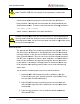
The forward RF power should be at least 80 watts if the battery
is normal. If it is lower than 80 watts check for proper cabling to
the power source. (See Section 3.2.2.1.)
If the reverse RF power is greater than 5 watts check the antenna and
coaxial cabling for proper installation.
If both the forward and reverse pow
er are low, the transmitter may be
automatically shutting down due to an antenna VSWR greater than 3:1.
Check the antenna and coaxial cabling for proper installation.
If the DET RF is greater than
–115 dBm (for example, -
110 dBm), the unit
rm properly but the latency time of the link will be increased.
Refer to Section 3.1 for reducing site noise conditions.
An overall figure of merit for the link performance is the XMIT to ACK ratio.
If this ratio is 3:1 or lower, the overall performance wi
ll be very good.
This completes the initialization and power
-
up sequence of the MCC
The unit is now ready for operation.
Refer to Chapter 4 for detailed operating instructions.
DCN
00001789-A
Do Not Distribute.
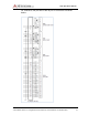
The following response will be displayed on the operator terminal:
rf resets
xxxx yyyy zzzz aaaa bbbb ccc ddd eee
Station.
This should be greater than 80 watts.
This should be less than 5 watts.
This should be
This will normally be the
120.
The forward RF power should be at least 80 watts if the battery
is normal. If it is lower than 80 watts check for proper cabling to
If the reverse RF power is greater than 5 watts check the antenna and
er are low, the transmitter may be
automatically shutting down due to an antenna VSWR greater than 3:1.
110 dBm), the unit
rm properly but the latency time of the link will be increased.
An overall figure of merit for the link performance is the XMIT to ACK ratio.
ll be very good.
up sequence of the MCC
-545C.