
User's Manual

545C Operations Manual
02/10/2012
34
© 2012 Meteorcomm LLC.
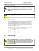
4.3 Power-
Up Sequence
Important:
Before applying power to the MCC
between the MCC-
545C and the external equipment (power, antenna,
operator terminal, and data logger). Refer to Section
instructions.
Caution
:
3.3 have been completed.
4.3.1
Operator Terminal
Connect a laptop or an operator terminal, with
the Operator Port
.
emulation program designed for interfacing with MCC products
operator terminal must be programmed with the same configuration
parameters as the Operator Port.
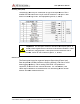
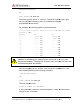
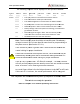
The Operator Port of the MCC
factory default configuration at the time of shipment:
Baud rate
9600
Parity
Data bits
8
Protocol
Stop bit
1
Flow control
4.3.2
Power Connection
Power up the MCC
-
Note:
When the unit
review Section 3.2.3.1 for proper cabling to the power source. The voltage
drop at the input connector during transmission should be less than 2 VDC
for proper operation of the unit. Verify this during the
Procedure in Section 3.4.
Prerelease
DCN
.
All Rights Reserved. Proprietary and Confidential. Do
Up Sequence
Before applying power to the MCC
-
545C, check all connections
545C and the external equipment (power, antenna,
operator terminal, and data logger). Refer to Section
3.2.3 for cabling
:
Disconnect the antenna cable until all steps in Section
3.3 have been completed.
Operator Terminal
Connect a laptop or an operator terminal, with
XTermW
installed, to
.
XTermW is an MCC windows-
based terminal
emulation program designed for interfacing with MCC products
operator terminal must be programmed with the same configuration
parameters as the Operator Port.
The Operator Port of the MCC
-
545C is programmed with the f
factory default configuration at the time of shipment:
Parity
no
Protocol
ASCII
Flow control
none
Power Connection
-
545C by applying +12VDC to the power connector.
When the unit
transmits, it will draw up to 20 amps; therefore,
review Section 3.2.3.1 for proper cabling to the power source. The voltage
drop at the input connector during transmission should be less than 2 VDC
for proper operation of the unit. Verify this during the
Operational Test
Procedure in Section 3.4.
DCN
00001789-A
Do Not Distribute.
545C, check all connections
545C and the external equipment (power, antenna,
3.2.3 for cabling
Disconnect the antenna cable until all steps in Section
installed, to
based terminal
emulation program designed for interfacing with MCC products
. The
operator terminal must be programmed with the same configuration
545C is programmed with the f
ollowing
545C by applying +12VDC to the power connector.
transmits, it will draw up to 20 amps; therefore,
review Section 3.2.3.1 for proper cabling to the power source. The voltage
drop at the input connector during transmission should be less than 2 VDC
Operational Test