
User's Manual

545C Operations Manual
02/10/2012
32
© 2012 Meteorcomm LLC.
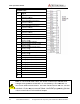
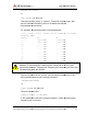
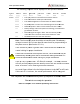
SENSOR PORT
Pin Signal
1
Optocoupled input #1 positive
( 500 ohm resistor)
2
Optocoupled input #1 return
3
Optocoupled input #2 positive
( 500 ohm
resistor)
4
Optocoupled input #2 return
5
Optocoupled input #3 positive
( 500 ohm resistor)
6
Optocoupled input #3 return
7
Optocoupled input #4 positive
( 500 ohm resistor)
8
Optocoupled input #4 return
9
Ground
10
Relay Output #1 Normally Open
(2 Amp rating)
11
Relay Output #1 Common
12
Relay Output #1 Normally Closed
(2 Amp rating)
13
Relay Output #2 Normally Open
(2 Amp rating)
14
Relay Output #2 Common
15
Relay Output #2 Normally Closed
(2 Amp
rating)
16
Switched +12V (battery)
17
Analog Input #1 ( 0 to 5 V)
18
Analog Input #2 ( 0 to 5 V)
19
Analog Input #3 ( 0 to 5 V)
20
Analog Input #4 ( 0 to 5 V)
21
Analog Input #5 ( 0 to 5 V)
22
Analog Input #6 ( 0 to 5 V)
23
+5V Ref (10mA for sensor excitation)
24
+12V (0.5A maximum)
25
Detected RF Test Point
Note: In -
03 series or later radios, the sensor connector pin #16 has been
changed from ground to a switched +12 volt
volt can be used to drive sensors. The total current load on the +12 volt and
switched +12 volt must not exceed 500mA. Use EVENT programming (Section
4.6) to control the +12 volt switched output.
Prerelease
DCN
.
All Rights Reserved. Proprietary and Confidential. Do
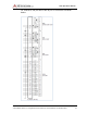
Optocoupled input #1 positive
( 500 ohm resistor)
Optocoupled input #1 return
Optocoupled input #2 positive
resistor)
Optocoupled input #2 return
Optocoupled input #3 positive
( 500 ohm resistor)
Optocoupled input #3 return
Optocoupled input #4 positive
( 500 ohm resistor)
Optocoupled input #4 return
Relay Output #1 Normally Open
(2 Amp rating)
Relay Output #1 Common
Relay Output #1 Normally Closed
(2 Amp rating)
Relay Output #2 Normally Open
(2 Amp rating)
Relay Output #2 Common
Relay Output #2 Normally Closed
rating)
Switched +12V (battery)
Analog Input #1 ( 0 to 5 V)
±0.5%
Analog Input #2 ( 0 to 5 V)
±0.5%
Analog Input #3 ( 0 to 5 V)
±0.5%
Analog Input #4 ( 0 to 5 V)
±0.5%
Analog Input #5 ( 0 to 5 V)
±0.5%
Analog Input #6 ( 0 to 5 V)
±0.5%
+5V Ref (10mA for sensor excitation)
+12V (0.5A maximum)
Detected RF Test Point
03 series or later radios, the sensor connector pin #16 has been
changed from ground to a switched +12 volt
(battery). This switched +12
volt can be used to drive sensors. The total current load on the +12 volt and
switched +12 volt must not exceed 500mA. Use EVENT programming (Section
4.6) to control the +12 volt switched output.
DCN
00001789-A
Do Not Distribute.
03 series or later radios, the sensor connector pin #16 has been
(battery). This switched +12
volt can be used to drive sensors. The total current load on the +12 volt and
switched +12 volt must not exceed 500mA. Use EVENT programming (Section