
User's Manual

02/10/2012
© 2012 Meteorcomm LLC. All Right
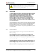
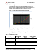
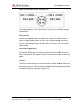
Figure 12: MCC
-
The voltage at pins 1 and 4 should not drop by more than 2VDC during
transmission.
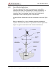
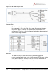
VHF Antenna
Connect the antenna cable to the BNC RF connector
used for cable lengths under 50 feet
214) for cable lengths up to 100 feet
cable length.
GPS Antenna (Opt
An external GPS antenna is required when the internal GPS receiver is
used.
Connect the GPS antenna cable to the SMA connector on the front
panel.
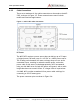
I/O Port
The 44 pin I/O connector on the front panel includes three RS
and one Sensor port
out these four ports as shown in Figure
545C Operations Manual
Prerelease
hts Reserved.
Proprietary and Confidential. Do Not Distribu
-
545C power connector pins
The voltage at pins 1 and 4 should not drop by more than 2VDC during
Connect the antenna cable to the BNC RF connector
. RG-
223 may be
used for cable lengths under 50 feet
.
Use a large diameter cable (RG
214) for cable lengths up to 100 feet
.
Refer to Section 3.1.5 for proper
GPS Antenna (Opt
ional)
An external GPS antenna is required when the internal GPS receiver is
Connect the GPS antenna cable to the SMA connector on the front
The 44 pin I/O connector on the front panel includes three RS
and one Sensor port
.
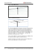
MCC provides a standard cable harness that breaks
out these four ports as shown in Figure
13:
545C Operations Manual
DCN 00001789-A
ibute.
29
The voltage at pins 1 and 4 should not drop by more than 2VDC during
223 may be
Use a large diameter cable (RG
-
Refer to Section 3.1.5 for proper
An external GPS antenna is required when the internal GPS receiver is
Connect the GPS antenna cable to the SMA connector on the front
The 44 pin I/O connector on the front panel includes three RS
-232 ports
MCC provides a standard cable harness that breaks