
User's Manual

545C Operations Manual
02/10/2012 Prerelease DCN 00001789-A
© 2012 Meteorcomm LLC. All Rights Reserved. Proprietary and Confidential. Do Not Distribute. 15
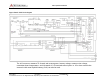
• Rx 1st local oscillator phase lock loop (47.7-60.7 MHz output, 10
kHz steps limited to 53.7 – 56.7 MHz in FCC ID: BIB54505003-01)
• Rx 2nd local oscillator phase lock loop (10.6 MHz)
• PIC Microcontroller
GMSK Modulator
• DSP digital baseband GMSK generator
• I and Q DACs
• I/Q Vector Phase Modulator (GMSK)
• Pre amplifier (+13 dBm output)
All components are mounted on an 8.5" by 3.5" two-sided printed circuit
board. All components are surface mounted.
3.5 Pre-Amp, Final Power Amp, and Power Control
This board contains two low-level amplifiers that amplify the +13 dBm
(10 mW) signal from the modulator to the 2 watts required by the final
power amplifier. A special power switch is used to control the rise and
fall times of the RF power output. A duty cycle limiter circuit limits the
duty cycle of the power amplifier to 16%. A temperature sensor is also
located on this board for monitoring the internal temperature of the
MCC-545C. This temperature reading may be transmitted to the Host for
maintenance purposes.
The 100 watt power amplifier is mounted inside an aluminum enclosure
to provide RF shielding between the low level phase lock loop
synthesizers and the high power output. This board contains a T/R
switch for half-duplex operation, a harmonic low pass filter, and a dual
directional coupler for power level control. The coupler measures
forward and reverse power. If the VSWR exceeds 3.0:1 the power
amplifier automatically shuts down. The power amplifier’s parameters
are also transmitted to the Host for maintenance purposes.
A switching regulator power supply provides 5.7 volts for the processor
and transceiver boards.