
User's Manual

545C Operations Manual
02/10/2012 Prerelease DCN 00001789-A
14 © 2012 Meteorcomm LLC. All Rights Reserved. Proprietary and Confidential. Do Not Distribute.
An internal lithium ion battery is used to maintain the internal real time
clock and battery backed RAM. This battery operates the clock in a
power down state for a period of approximately 6 months. This battery
should be removed if the unit is stored for extended periods of time.
In -03 or later versions of the units, the lithium ion battery has been
replaced with a rechargeable nickel metal hydride battery. This battery
is located at the rear of the unit with Velcro. (You have to open the
rear lid to get access to it.) A short jumper is used to connect the
battery to the processor board. This jumper should be removed if the
unit is stored for long periods of time (longer than 2 months). The
battery must be connected before the unit will start operating.
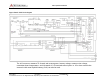
3.4 Transceiver
The transceiver assembly contains a receiver, transmit and receive
frequency synthesizers, and a modulator. The MCC-545C receiver and
modulator support 9.6 kbps Gaussian Minimum Shift Keying (GMSK).
GMSK Receiver
• Input bandpass filter (37-50 MHz )
• RF amplifier (17 dB)
• Low pass image filter (Fc=50 MHz)
• Mixer
• IF amplifiers and filters (10.7 MHz)
• Noise blanker
• Mixer, 2nd IF filter and amplifier (100 kHz), and RSSI circuit
• Phase lock loop frequency discriminator
• GMSK bit detector and clock generator
Synthesizer (1st and 2nd local oscillator and transmit oscillator)
• Reference Oscillator (12.8 MHz +/- 2.5 PPM)
• Tx phase lock loop (74-100 MHz output, 20 kHz steps)
(86-92 MHz, 20 kHz steps in FCC ID: BIB54505003-01)
• A divide by 2 circuit (37-50 MHz output, 10 kHz steps)
(43-46 MHz, 10 kHz steps in FCC ID: BIB54505003-01)