
User's Manual

545C Operations Manual
02/10/2012 Prerelease DCN 00001789-A
© 2012 Meteorcomm LLC. All Rights Reserved. Proprietary and Confidential. Do Not Distribute. 11
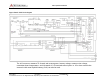
3.2 Printed Circuit Board Assemblies
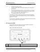
The MCC-545C contains three printed circuit board assemblies as shown
in Figure 2.2.
3.2.1 Microprocessor
The low-power 32-bit microprocessor controller performs the radio
control, link, and network protocol functions. This assembly also
contains a digital signal processor (DSP) and digital-to-analog converter
(DAC) for generating the in-phase (I) and quadrature-phase (Q) base
band signals for generating the GMSK RF signal.
3.2.2 Transceiver
The selectable-rate transceiver uses a vector phase modulator (+13DBm
output) and frequency synthesizers to produce 9.6 kbps.
3.2.3 Power Amplifier
Note: The nominal RF power amplifier rating of the MCC-545C is 100W
or 50 dBm. The output power is calibrated at the factory at the
expected operating frequency. Measured power values may vary up to 1
dB from rated power, up to 51 dBm or 125W over the frequency range
of the radio.
The multi-stage power amplifier includes a 2 watt, 2-stage preamplifier;
a 100 watt, solid-state, 2-stage power amplifier; and a power switch.
A 12-channel GPS receiver may be mounted on the processor board as
an optional subassembly.
All components are soldered in place using surface mount technology.
As an option, the boards can be conformal coated with an acrylic
encapsulate that contains a tropicalizing, anti-fungal agent to provide
additional protection against moisture and contamination.