
User's Manual

545C Operations Manual
02/10/2012 Prerelease DCN 00001789-A
102 © 2012 Meteorcomm LLC. All Rights Reserved. Proprietary and Confidential. Do Not Distribute.
not triggered when the voltage crosses the 5.0 level in the downward
direction, only the upward direction. If one wants to detect both voltage
crossings, there should be two events defined, one to detect the positive
change (ADCHI), and one to detect the negative change (ADCLOW).
The settling and hold-off durations are programmable for each scanned
event. They are specified in clock-tick counts where each tick is 62.5
milliseconds, or 1/16 second. Because these durations are programmable,
scanned event hysteresis is fully controllable. Given the 62.5 millisecond
sampling rate, events are limited to those that persist longer than 62.5
milliseconds but shorter than about an hour duration. Similarly, hold-off
times between events must also persist longer than 62.5 milliseconds.
Attempting to program events that are briefer than 62.5 milliseconds will
prove unreliable. It is important to remember that a scanned event must
change slow enough that the event monitor can sample the input line
reliably.
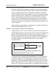
The external I/O expander (XIO) has its own processor to scan its event
definition table. Its internal “clock-tick” will be set to one millisecond per
increment. The MCC-545C will configure the XIO when event commands are
processed from the script file. The XIO will monitor its own events and send
changes to the MCC-545C using a serial interface.
Discrete Event
A discrete event is determined by whether or not a discrete input signal
remains either high or low for the given settling duration. “high” or “low”
is a part of the event definition set by the operator. The end of a discrete
event occurs when the signal has persistently returned to its previous low
or high state for the hold-off duration. For RS-232 signals, “high” is
considered the ON state and “low” the OFF state. “high” is also known as
SET; “low” as CLR.
The high/low convention follows the voltage level of the input signal. For
TTL signals, “high” is a +5 volt level, and “low” is zero volts. For the RS-
232 modem-control signals, “high” is +10 volts and “low” in -10 volts. For
the GPS input, a “high” is when the GPS is at “V1” or “V2” status, and
“low” is when there is no GPS characters being received at the RS-232 port
or when the GPS is at the “V0” status. The NET input is “high” when the RF
modem is online to a Base or Repeater that is connected to a host system.