
Installation Guide

2
FP Panel Instructions
IB519062EN www.eaton.com
For T-Grid Mounting
1. Turn off the power at the main fuse/breaker box.
2. Carefully open carton and remove panel from
packaging.
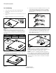
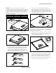
3. Locate fixture junction box cover and slide to remove it
(Fig. 1).
4. Remove appropriate knockout(s) for power supply
wiring.
NOTE: Fixture weights are below. Ensure grid location
is rated for fixture weight before moving to next step. If
unsure use cable to support fixture to appropriate support
beam above fixture using the circular holes in the corner
tabs (Fig 2).
5. Pass fixture through the grid at a 45 degree angle and
lay fixture into the grid (Fig. 3).
FP Panel Instructions
Figure 2.
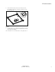
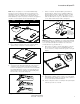
6. Grid clips are provided for additional retention to ceiling
system. Orient 4 tabs on back of fixture over T-GRID
by bending tabs up 90 degrees perpendicular to back
of fixture. Next bend tabs 90 degrees towards T-GRID
frame (Fig. 4).
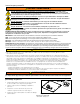
7. Using the open knockout bring in the supply line. Using
the three provided wire nuts to attach the ground wire
to the ground supply wire, the black (line) wire to the
black supply wire, and the white (neutral) wire to the
white supply wire (Fig. 5).
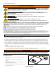
NOTE: This fixture is compatible with 0-10V dimming. If
installing dimming wires follow your dimmer instructions for
wiring to the violet (Dim +) and grey (Dim –) leads.
NOTE: This fixture is compatible with battery backup sys-
tems including the Surelites EBPLED7W and EBPLED14W.
If using a battery backup system remove driver cover plate
to access LED load wires and follow battery backup wiring
instructions (Fig. 5). Ensure driver cover plate is reinstalled
after wiring.
Figure 4.
Figure 5.
2' x 2' 1' x 4' 2' x 4'
9.4lbs (4.2kg) 9.8lbs (4.4kg) 18.5lbs (8.4kg)
Figure 1.
Figure 3.
Wire nuts (3)
supply
black
white
ground
For battery
backup,
access LED
wires here
push