
Instructions / Assembly

Instruction Manual/Instrucciones/Directives
Questions?/¿Preguntas?/Questions ? 1-800-334-6871 ConsumerProducts@eaton.com
1
determined by turning the equipment off and on, the user is encouraged to try to correct the
interference by one or more of the following measures:
- Reorient or relocate the receiving antenna.
- Increase the separation between the equipment and receiver.
- Connect the equipment into an outlet on a circuit different from that to which the
receiver is connected.
- Consult the dealer or an experienced radio/TV technician for help.
WARNING: FCC Regulations state that any unauthorized changes or
modifications to this equipment not expressly approved by the manufacturer
could void the user’s authorization to operate this equipment.
SAVE THESE INSTRUCTIONS.
INSTALLATION INSTRUCTIONS
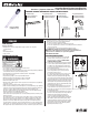
1. Before installation, plug fixture (A) into a 120V, 60Hz
electrical outlet to check for proper operation. Then
unplug and begin the installation. DO NOT ATTEMPT
TO INSTALL WHILE PLUGGED IN.
2. Product may be suspended mounted or bracket mounted
to either a stud or dry wall. Mounting hardware should
be suitable for the intended application and mounted
32” apart for chain mount applications and 24” apart for
bracket mount applications.
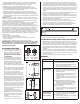
A. For stud chain mount applications (Fig. 1) insert
(2) #8 or larger diameter open screw eye hooks into
a wood joist. Continue to step 3.
B. For drywall mount applications (Fig. 1) drill a 1/2 inch
hole into the ceiling. Using a 3/16 or larger diameter
threaded eyebolt (sold separately) thread toggle wings
onto threads. Fold wings against threaded eyebolt ensuring
wings fold towards the eye of the bolt. Next push the wings
through the drilled hole until spring opens wings on back
side of drywall. Pull eyebolt down to allow wings to grab
the drywall. Turn the eyebolt clockwise tightening eyebolt
against drywall. Continue to step 3.
C. For stud bracket mount applications (Fig. 5) insert #8
or larger diameter wood screws through center hole on
bracket and secure bracket to wood joist ensuring bracket
is perpendicular to fixture.
D. For drywall bracket mount applications (Fig. 1) drill a 1/2
inch hole into the ceiling. Using a 3/16 or larger diameter
threaded bolt (sold separately) pass bolt through
center hole in bracket and thread toggle wings onto
threads. Fold wings against threaded bolt ensuring wings
fold towards the head of the bolt. Next push the wings
through the drilled hole until spring opens wings on back
side of drywall. Pull bolt down to allow wings to grab the
drywall. Turn the eyebolt clockwise tightening bracket
against drywall. Continue to step 6.
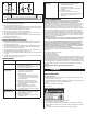
PACKAGING CONTENTS/CONTENIDO DEL PAQUETE/CONTENU DU PAQUET
ITEMS REQUIRED
(Purchase separately)
• Drywall mount - (2) 3/16 or larger diameter toggle eyebolts 2 7/8” long with
(2) tapered wings.
• Pliers
• Drill for Drywall mount
• (2) Eye Screws
WARNINGS AND CAUTIONS
• For suspended or bracket mount only, Do not surface mount.
• Do not install on a radiant-heating ceiling.
• For suspended mount only using integral hooks or direct mount using brackets provided. Do
not mount fixture where it touches the mounting surface.
• Operating ambient room temperature should be between -20˚C and 40 ˚C
• Do not use in wet location.
• Only install using length of chain as provided with luminaire.
• Minimum operating room temperature of -20˚C recommended.
• This unit is intended to be installed directly below receptacle.
• Never alter length of power cord.
• Mounting hooks should engage the chain only, product is not intended to be suspended by
the electric cord set.
• Fixture must be mounted directly below ceiling mounted receptacle.
• Fixture should be installed by persons with experience in household wiring or by a qualified
electrician. The electrical system, and the method of electrically connecting the fixture to it,
must be in accordance with the National Electrical Code and local building codes.
This device complies with Part 15 of the FCC Rules and Rss-210 of the industry Canada.
Operation is subject to the following two conditions
1) This device may not cause harmful interference, and
2) This device must accept any interference received, including interference that may cause
undesired operation
This equipment has been tested and found to comply with the limits for a Class B digital
device, pursuant to Part 15 of the FCC Rules. These limits are designed to provide reason-
able protection against harmful interference in a residential installation. This equipment
generates, uses and can radiate radio frequency energy and if not installed and used in
accordance with the instructions, may cause harmful interference to radio communications.
However, there is no guarantee that interference will not occur in a particular installation. If
this equipment does cause harmful interference to radio or television reception, which can be
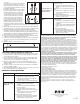
A. Fixture housing
Carcasa de la lámpara
Boîtier du luminaire
ENGLISH
B. (2) Mounting chains
(2) Cadenas de instalación
(2) Chaînes de montage
Toggle bolt
Open screw eye
Joist
1
4SHP3240BTS
(3200 lumens)
2
A
B
C. Switch pull string
Cuerda interruptor
Corde de commutateur
#8 or
larger open
screw eye
3/16 or
larger
toggle bolt
D. (2) Mounting Bracket
(2) Soporte de montaje
(2) Support de montage
E. (2) S-hook
(2) Crochet en S
(2) Gancho en S
F. (2) Eye Screws
(2) Vis à oeillet
(2) Tornillo de ojo