
Manual

Operating Instructions – MOVIMOT® MM03C - MM3XC
89
7
Additional information for mounting close to the motor
Startup of Standard Design
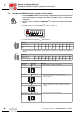
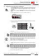
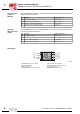
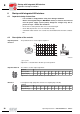
DIP switch
With mounting of the MOVIMOT
®
inverter close to the motor, set DIP switch S1/5 to ON
which is different than the factory setting.
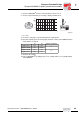
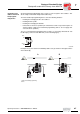
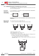
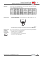
Braking resistor
• With motors without brakes, an internal braking resistor (BW1 or BW2) must be con-
nected to the MOVIMOT
®
.
• With brake motors, no braking resistor may be connected to the MOVIMOT
®
.
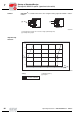
Mounting of the
MOVIMOT
®
inverter in the
field distributor
Observe the instructions in the corresponding manuals when mounting the MOVIMOT
®
inverter close to the motor in the field distributor:
• PROFIBUS Interfaces, Field Distributors
• InterBus Interfaces, Field Distributors
• DeviceNet/CANopen Interfaces, Field Distributors
• AS-Interfaces, AS-i field distributors
S1 1 2 3 4 5
Motor
protec-
tion
6
Motor
rating class
7
PWM
frequency
8
No-load
damping
Message RS-485 address
2
0
2
1
2
2
2
3
ON 1111 Off
Motor one
size smaller
Variable
(16, 8, 4 kHz)
On
OFF 0000 On adapted 4 kHz Off
06487AXX
13
14
15
BW1 / BW2
MOVIMOT
®
00
I