
Manual

88
Operating Instructions – MOVIMOT® MM03C - MM3XC
7
Additional information for mounting close to the motor
Startup of Standard Design
7.10 Additional information for mounting close to the motor
If the MOVIMOT
®
inverter with option P2.A is mounted close to the motor, you need to
observe the following instructions:
Checking the
method of con-
nection for the
connected motor
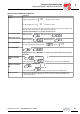
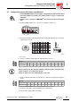
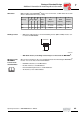
Use the following figure to verify that the selected connection method of MOVIMOT
®
is
identical for the connected motor.
Important: For brake motors: Do not install brake rectifiers inside the terminal box
of the motor!
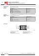
Motor protection
and direction of
rotation enable
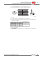
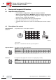
The connected motor must be equipped with a TH.
• If control is carried out via RS-485, the TH must be wired as follows:
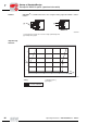
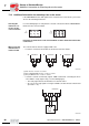
• If control is carried out via binary signals, SEW recommends connecting the TH in
series with the "ready signal" relay (see the following figure).
– The ready signal must be monitored be an external control.
– As soon as the ready signal is no longer available, the drive must be switched off
(tl. R and L = "0").
03636AXX
U1 V1 W1
W2 U2 V2
U1 V1 W1
W2 U2 V2
댴 쑶
52257AXX
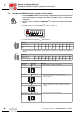
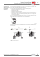
[A] Both directions of rotation are enabled
[B] Only counterclockwise direction of rotation is enabled
[C] Only clockwise direction of rotation is enabled
52253AXX
24V
L
R
24V
L
R
24V
L
R
TH
TH
TH
MOVIMOT
®
MOVIMOT
®
MOVIMOT
®
A
BC
TH
SPS
24V
K1a
K1b
L
R
MOVIMOT
®
00
I