
Manual

86
Operating Instructions – MOVIMOT® MM03C - MM3XC
7
Startup with external AS-i binary slave MLK11A
Startup of Standard Design
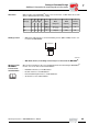
Data from AS-i
master to
MLK11A
The following table shows the 4 data bits that are transferred from the AS-i master to the
MLK11A via the AS-Interface:
Data from
MLK11A to AS-i
master
The following table shows the 4 data bits that are transferred from the MLK11A to the
AS-i master via the AS-Interface:
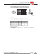
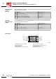
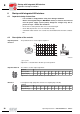
LED display
Bit Function Display / LED color
D0 Clockwise (terminal R) DO 0 / yellow
D1 Counterclockwise (terminal L) DO 1 / yellow
D2 Speed f1 / speed f2 (terminal f1/ f2) DO 2 / yellow
D3 Voltage supply / reset (terminal 24 V) DO3 / green
Bit Function Display / LED color
D0 Ready signal (relay K1) DI 0 / yellow
D1 --
D2 Sensor 1 (M12 socket, pin 4) DI 2 / yellow
D3 Sensor 2 (M12 socket, pin 2) DI 3 / yellow
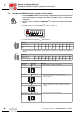
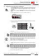
05070BXX
[1] MOVIMOT
®
ready for operation
[2] External input DI2
[3] External input DI3
[4] Voltage supply via AS-i system is ok
[5] Clockwise rotation activated
[6] Counterclockwise rotation activated
[7] Speed f2 activated
[8] MOVIMOT
®
voltage supply
DI0
DI2
DI3
AS-i
Power
DO0
DO1
DO2
DO3
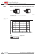
[1]
[2]
[3]
[4]
[5]
[6]
[7]
[8]
00
I