
Manual

Operating Instructions – MOVIMOT® MM03C - MM3XC
85
7
Startup with external AS-i binary slave MLK11A
Startup of Standard Design
7.9 Startup with external AS-i binary slave MLK11A
1. Isolate MOVIMOT
®
drive from the supply, safeguarding it against unintentional
power-up! Dangerous voltages may still be present for up to 1 minute after
shutdown!
2. Review correct connection of MOVIMOT
®
(see the section "Electrical Installa-
tion").
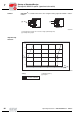
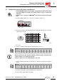
3. Ensure that DIP switches S1/1 – S1/4 are set to OFF (= address 0).
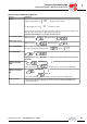
4. Set first speed with f1 setpoint potentiometer (activated if terminal f1/f2 = '0') (factory
setting: approx. 50 Hz).
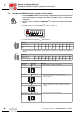
5. Set the second speed with switch f2 (active when tl. f1/f2 = "1").
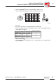
6. Set the ramp time with switch t1 (ramp times in relation to a setpoint step change of
50 Hz).
7. Place the MOVIMOT
®
inverter on the terminal box and secure it.
8. Re-insert screw plug of setpoint potentiometer f1 with gasket.
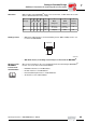
9. Connect AS-i supply voltage and supply.
05062AXX
05066BXX
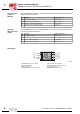
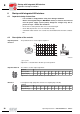
[1] Pot. position
Switch f2
Detent position012345678910
Setpoint f2 [Hz] 5 7 10 15 20 25 35 50 60 70 100
1
ON
6
7
8
543
2
1
ON
432
123456789100
100
f [Hz
[1]
]
2
75
25
50
6
5
f
1
3
4
5
6
7
8
During operation, the first speed is infinitely variable using the setpoint potenti-
ometer f1 which is accessible from outside.
Speeds f1 and f2 can be set independently to any value.
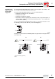
Switch t1
Detent position 012345678910
Ramp time t1 [s] 0.1 0.2 0.3 0.5 0.7 1 2 3 5 7 10
3
4
5
6
7
8
00
I