
Manual


8
Operating Instructions – MOVIMOT® MM03C - MM3XC
3
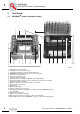
MOVIMOT® inverter (standard design)
Unit Design
3Unit Design
3.1 MOVIMOT
®
inverter (standard design)
06496AXX
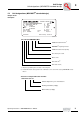
1. Identification of the circuit type
2. Terminal box (size 2 used as example)
3. Connection plug between connection unit and inverter
4. MOVIMOT
®
inverter with heat sink (size 2 used as example)
5. Connection unit with terminals
6. Screw for PE connection
댷
7. Electronics terminal strip X2
8. Internal braking resistor BW. (standard for motors without brake)
9. Connection of brake coil (X3). For motors without brake: Connection of internal
braking resistor BW. (standard)
10. Mains connection L1, L2, L3 (X3) (suitable for 2 x 4 mm
2
)
11. Screw for PE connection
댷
12. Cable glands
13. Electronics nameplate
14. Safety hood for inverter electronics
15. Setpoint potentiometer f1 (not visible), accessible from top of MOVIMOT
®
inverter
via screw fitting
16. Setpoint switch f2 (green)
17. Switch t1 for generator ramp (white)
18. DIP switches S1 and S2 (for settings see the section "Startup")
19. Status LED (visible from top of MOVIMOT
®
inverter, see the section "Diagnostics")
1
2
34
5
6
7
8
910
11 12
13
14 15 16
17
18
19