
Manual

68
Operating Instructions – MOVIMOT® MM03C - MM3XC
7
Selectable special functions MM..C-503-00
Startup of Standard Design
Terminal operation
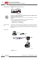
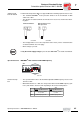
Mechanical brake controlled by MOVIMOT
®
• Terminals 13, 14 and 15 are assigned to the brake coil of the mechanical brake at
the wiring board of MOVIMOT
®
.
• The mechanical brake cannot be influenced by the terminals. The brake works anal-
ogous to a unit without special function.
• The relay is switched as ready relay (standard function).
Mechanical brake controlled by relay output
• A braking resistor (BW..) must be connected to terminal 13 and 15 at the wiring board
of MOVIMOT
®
, terminal 14 is not assigned.
• The relay functions as brake control relay so that the ready signal function is no long-
er available (it is imperative that you observe section "Use of relay output with special
function 7 + 9" starting on page 75).
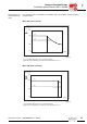
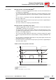
Special function 8
MOVIMOT
®
with minimum frequency 0 Hz
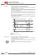
Function descrip-
tion
Control via RS-485:
If switch f2 is in position of rest 0, the minimum frequency measures 0 Hz with activated
special function. All other adjustable values remain unchanged.
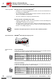
Control via terminals:
If switch f2 is in position of rest 0, the setpoint f2 measures 0 Hz with activated special
function. All other adjustable values remain unchanged.
Important: The rapid stop function cannot be used in terminal operation!
05603AXX
1
6
7
85
4
3
2
ON
S2
6
7
85
3
4
5
6
7
8
Switch f2
Detent position 0 12345678910
Minimum frequency [Hz]
with activated special function
0 5 7 10 12 15 20 25 30 35 40
Minimum frequency [Hz]
without special function
2 5 7 10 12 15 20 25 30 35 40
Switch f2
Detent position 0 12345678910
Setpoint f2 [Hz]
with activated special function
0 7 10 15 20 25 35 50 60 70 100
Setpoint f2 [Hz]
without special function
5 7 1015202535506070100
3
4
5
6
7
8
00
I