
Manual

Operating Instructions – MOVIMOT® MM03C - MM3XC
53
7
Description of the DIP switches S1
Startup of Standard Design
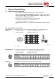
7.3 Description of the DIP switches S1
DIP switches
S1/1-S1/4
Selection of RS-485 address of MOVIMOT
®
via binary coding
Depending on the control of MOVIMOT
®
, different addresses must be set:
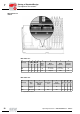
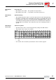
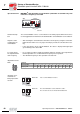
DIP switches
S1/5
Motor protection activated or deactivated
• If the MOVIMOT
®
inverter is mounted close to the motor (with option P2.A or in the
field distributor), the motor protection must be deactivated.
• To ensure motor protection after all, a TH (bimetallic thermostat) must be used. In
this case, the TH opens the sensor circuit after reaching the nominal response tem-
perature (see the "Startup with field distributor" section in the "Drive System for De-
centralized Installation" system manual).
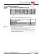
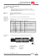
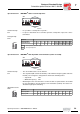
Decimal
Address
0 1 2 3 4 5 6 7 8 9 10 11 12 13 14 15
S1/1 – X – X – X – X – X – X – X – X
S1/2 ––
X X ––X X ––X X ––X X
S1/3 ––––
X X X X ––––X X X X
S1/4 ––––––––
X X X X X X X X
X = ON
–= OFF
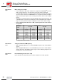
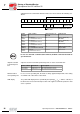
Control RS-485 address
Binary control (terminal operation) 0
Via external AS-i binary slave (MLK11A) 0
Via keypad (MLG.., MBG..) 1
Via fieldbus interface (MF..) 1
Via fieldbus interface with integrated small control system (MQ..) 1 to 15
Via RS-485 master 1 to 15
00
I