
Manual

Operating Instructions – MOVIMOT® MM03C - MM3XC
43
6
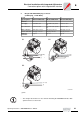
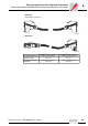
Connection of MOVIMOT® MM../AZSK (connection option B)
Electrical Installation with Integrated AS-Interface
6.4 Connection of MOVIMOT
®
MM../AZSK (connection option B)
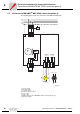
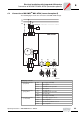
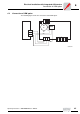
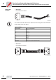
The following figure shows the connection of the MM../AZSK design.
52061AXX
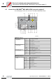
AZSK plug connector
[1] M12 plug connector
(plug, black)
1 24 V 24 V supply (AUX-PWR)
2 N.C. Not assigned
3 0 V AUX-PWR reference potential
4 N.C. Not assigned
[2] M12 plug connector
(plug, yellow)
1 AS-i + AS-i data cable +
2 0 V AUX-PWR reference potential
3 AS-i - AS-i data cable -
4 24 V 24 V supply (AUX-PWR)
[3] M12 plug connector
(socket, black)
1 VO24 24 V voltage supply for sensors
2 DI3 Sensor input DI3
3VO⊥ 0 V reference potential for sensors
4 DI2 Sensor input DI2
M
3~
L1
L2
L3
PE
K11
F11/F12/F13
13
14
15
L1
L2
L3
BMG
RD
WH
BMG
BL
BW
.
4
2
1
3
3
1
4
2
24V
4
2
1
3
4
2
1
3
3
1
4
2
AS-I+
AS-I -
24 V
DI3
VO24
3
1
4
2
DI2
[1]
[2]
[3]
BK
YE
BK
VO
MM../AZSK