
Manual

30
Operating Instructions – MOVIMOT® MM03C - MM3XC
5
Connection MOVIMOT® options
Electrical Installation of MOVIMOT® Standard Design
Connection of
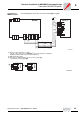
URM option
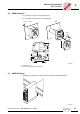
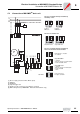
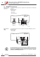
The following figure shows the connection of the URM option.
Connection of
MDG11A option
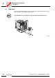
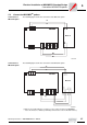
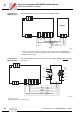
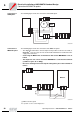
The following figure shows the connection of the MDG11A option.
• The diagnostic unit must be connected prior to the possible occurrence of a fault, as
MOVIMOT
®
error messages are not saved and the information is lost when the 24 V
supply is disconnected.
• Connecting the MDG11A to an RS-485 bus with several MOVIMOT
®
is not al-
lowed.
• The diagnostic unit can be used if the MOVIMOT
®
is controlled via terminals
(= address 0 [S1/1-S1/4 = OFF]).
• Do nut use the diagnostic unit if setpoint setting takes place via the RS-485 in-
terface.
52203AXX
M
3~
13
RD
14
15
24V
R
L
f1/f2
K1a
K1b
RS-
RS+
BMG
URM
13
14
15
WH
BU
L1
L2
L3
MOVIMOT
®
03404CXX
[1] EMC metal cable gland
For operation see the section "Diagnostics"
MDG11A
24V
RS+
RS-
댷
13
14
15
L1
L2
L3
24V
R
L
f1/f2
K1a
K1b
RS-
RS+
MOVIMOT
®
[1]