
Manual

26
Operating Instructions – MOVIMOT® MM03C - MM3XC
5
MOVIMOT® plug connectors
Electrical Installation of MOVIMOT® Standard Design
5.3 MOVIMOT
®
plug connectors
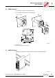
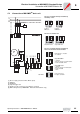
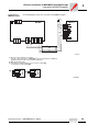
AVT1, ASA3 plug
connectors
The following illustration shows the assignment of the optional AVT1 and ASA3 plug
connectors.
Available designs:
• MM.../ASA3
• MM.../AVT1
• MM.../ASA3/AVT1
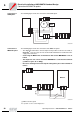
Plug connector
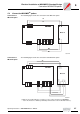
AMA6
The following illustration shows the assignment of the optional AMA6 plug connector.
Available design:
• MM.../AMA6
52113AXX
12345
6789
12
4
3
MOVIMOT
®
L1 L2 L3
24V RS+ RS-
ASA3
AVT1
10
52114AXX
MOVIMOT
®
AMA6
1
2
3
4
5
6
1
2
A
C
3
4
5
6
24 V
RS+
RS-
L2
L1
L3
For designs with plug connectors, both directions of rotation are enabled at the
factory. If only one direction of rotation is desired, please observe the section
"Connection of MOVIMOT
®
Basic Unit, Functions of the CW/STOP, CCW/STOP
terminals in control via RS-485 interface."