
Manual

16
Operating Instructions – MOVIMOT® MM03C - MM3XC
4
MOVIMOT® gearmotor
Mechanical Installation
4 Mechanical Installation
4.1 MOVIMOT
®
gearmotor
Before you begin
Install MOVIMOT
®
only if
• the entries on the nameplate of the drive match the voltage supply system,
• the drive is undamaged (no damage caused by transport or storage).
• it is certain that the following requirements have been fulfilled:
– Ambient temperature between –25 °C and +40 °C (remember that the tempera-
ture range of the gear unit may be restricted → operating instructions for the gear
unit)
– No oil, acid, gas, vapors, radiation, etc.
Installation toler-
ances
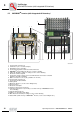
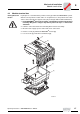
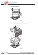
Mounting
MOVIMOT
®
• The MOVIMOT
®
may only be mounted or installed in the specified mounting position
on a level, vibration-proof and torsionally rigid support structure.
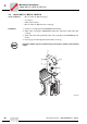
• Thoroughly remove anti-corrosion agents from the shaft extensions (use a commer-
cially available solvent). Do not allow the solvent to penetrate the bearings and shaft
seals – this could cause material damage!
• Carefully align MOVIMOT
®
and the driven machine, to avoid placing any unaccept-
able strain on the motor shafts (observe permissible overhung load and axial thrust
data!).
• Do not butt or hammer the shaft end.
• Use an appropriate cover to protect motors in vertical mounting positions from ob-
jects or fluids entering!
• Ensure an unobstructed cooling air supply and that air heated by other apparatus
cannot be drawn in or reused.
• Balance components for subsequent mounting on the shaft with a half key (output
shafts are balanced with a half key).
• Any condensation drain holes are closed with plastic plugs and must not be opened
unless needed.
• Do not leave any condensation drain holes open, since this defeats higher enclosure
ratings.
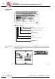
Installation in
damp areas or in
the open
• Use suitable screwed cable glands for the supply leads (use reducing adapters if
necessary).
• Coat the threads of cable glands and pocket caps with sealant and tighten them well
– then coat them again.
• Seal the cable entry well.
• Clean the sealing faces of the MOVIMOT
®
inverter well before re-assembly.
• Restore the anticorrosive coating if necessary.
• Check the type of enclosure is authorized (refer to the nameplate).
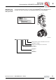
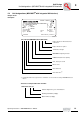
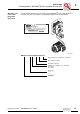
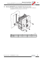
Shaft end Flanges
Diametric tolerance in accordance with DIN 748
• ISO k6 at ∅ ≤ 50 mm
•ISO m6 at ∅ > 50 mm
(Center bore in accordance with DIN 332, shape
DR)
Centering shoulder tolerance in accordance with
DIN 42948
•ISO j6 at ∅ ≤ 230 mm
• ISO h6 at ∅ > 230 mm