
Manual

152
Operating Instructions – MOVIMOT® MM03C - MM3XC
12
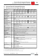
Technical data of options
Technical Data of Standard Design
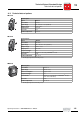
MWA21A
MDG11A
BGM brake recti-
fier
Important: The brake coil must correspond to the supply voltage
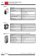
MWA21A option
Part number 823 006 4
Input voltage 24 V
DC
± 25 %
Current consumption approx. 70 mA
Serial interface
1)
1) with integrated dynamic terminating resistor
RS-485 for connecting max. 31 MOVIMOT
®
inverters
(max. 200 m, 9600 baud)
Unidirectional communication
Cycle time: 100 ms
Analog input 0...10 V / 2...10 V, R
i
≈ 12 kΩ
0...20 mA / 4...20 mA, R
i
≈ 22 Ω
Setpoint resolution of the analog input 8 bit ( ± 1 bit)
Signal level of binary inputs +13 V...+30 V = '1'
- 3 V ...+5 V = “0”
Enclosure IP 20
Ambient temperature -15...60 °C
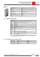
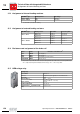
MDG11A option
Part number 822 941 4
Input voltage 24 V
DC
± 25 %
Current consumption approx. 70 mA
Serial interface RS-485 for connection of one MOVIMOT
®
inverter with
control via terminals
Enclosure IP 65
Ambient temperature -15...60 °C
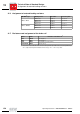
BGM brake rectifier
Part number 827 602 1
Enclosure IP20
Rated supply voltage
(black connecting leads)
230 V
AC
...500 V
AC
, +10% / -15%
50 Hz...60 Hz, ± 5%
Control voltage
(red / blue connecting leads)
+13 V...+30 V = "1“
-3 V...+5 V = "0“
Brake current
(brake connection 13, 14, 15)
max. 0.8 A
DC
Ambient temperature -25...60 °C
P
i
f
kVA
Hz
n