
Manual


Operating Instructions – MOVIMOT® MM03C - MM3XC
131
10
Diagnostics of MOVIMOT® standard design
Diagnostics
Diagnostics proce-
dure
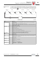
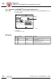
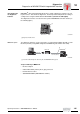
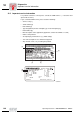
The diagnostic unit can display different information such as operating status, motor cur-
rent, status of input terminals, status of message relay and brake. The selection is made
by pressing the button . If a fault occurs, the fault number is automatically displayed.
Motor cur-
rent
Brake Relay Terminal R Terminal L Terminal f1/f2
Operational status 05623AXX
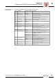
Display Message
Operational status --- No communication no 24 V at MOVIMOT
®
or RS-485 connection is incorrect (interrupted or
switched cable)
c 0 Not ready supply voltage is missing, but 24 V are present
c 2 Ready for operation supply voltage and 24 V are present, but no enable signal at terminal R or L
c 4 Enabled with motor rotating
Fault codes F01 Short circuit of inverter output
F06 Mains phase fault
F07 DC link voltage too high
F11 Thermal overload of the output stage
F84 Thermal overload of the motor or motor blocked
F89 Thermal overload of the brake or internal resistance of the brake not correct
F90 Assignment motor–inverter incorrect (e.g. MM03 – DT71D4
쑶)
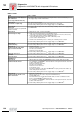
Motor current 0...180 Displays percentage of inverter nominal current, from 0% to 180%
Brake o10 Brake applied
o11 Brake released
Relay o20 Inverter not ready for operation (supply voltage is missing or inverter is in "fault" condition, see
Operating States or Fault Codes)
o21 Inverter ready
Terminal R i10 Terminal R = "0"
i11 Terminal R = "1" = CW rotation
Terminal L i20 Terminal L = "0"
i21 Terminal L = "1" = CCW rotation
Terminal f1/f2 i30 Terminal f1/f2 = "0" = Setpoint f1 active
i31 Terminal f1/f2 = "1" = Setpoint f2 active
c _
_ _ _ o 1 _ o 2 _ i 1 _ i 2 _ i 3 _