
Manual

Operating Instructions – MOVIMOT® MM03C - MM3XC
127
10
Diagnostics of MOVIMOT® standard design
Diagnostics
10 Diagnostics
10.1 Diagnostics of MOVIMOT
®
standard design
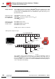
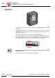
Status LED
The status LED is located on the top of the MOVIMOT
®
inverter (see the following
figure).
Meaning of the sta-
tus LED states
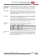
The three-color LED signals the operating and fault states.
50867AXX
[1] MOVIMOT
®
status LED
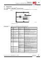
[1]
LED
color
LED status Operational status Description
– Off Not ready No 24 V power supply
Yel-
low
Steady flashing Not ready Self-test phase active or 24 V power supply present
but supply voltage not OK
Yel-
low
Steady, fast flashing Ready Releasing the brake without active drive enable
(only with S2/2 = "ON")
Yel-
low
Steady light Ready,
but unit is inhibited
24 V power supply and supply voltage OK,
but no enable signal
Green
/yel-
low
Flashing with alter-
nating colors
Ready,
but timeout
Faulty communication with cyclical data exchange
Green Steady light Unit enabled Motor in operation
Green Steady, fast flashing Current limit active Drive has reached the current limit
Red Steady light Not ready Check the 24 V
DC
supply.
Make sure that there is a smoothed DC voltage with
low ripple (residual ripple max. 13%) present.
Red 2 x flash, pause Fault 07 DC link voltage too high
Red Flashing slowly Fault 08 Fault speed monitoring (only with S2/4="ON")
Fault 90 Assignment of motor – inverter incorrect
(e.g. MM03 – DT71D4
쑶)
Fault 17 to 24, 37 CPU fault
Fault 25, 94 EEPROM error
Red 3 x flash, pause
Fault 01 Overcurrent of output stage
Fault 11 Excessive temperature in output stage
Red 4 x flash, pause Fault 84 Excessive temperature in motor
Assignment of motor to frequency inverter incorrect
Red 5 x flash, pause Fault 89 Excessive temperature in brake
Assignment of motor to frequency inverter incorrect
Red 6 x flash, pause Fault 06 Mains phase fault
00
I