
Manual

Operating Instructions – MOVIMOT® MM03C - MM3XC
105
8
Startup procedure
Startup with Integrated AS-Interface
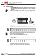
Data from
AS-i-Master
→
MOVIMOT
®
The following table shows the 4 data bits that are transferred from the AS-i master to the
MOVIMOT
®
via the AS-Interface:
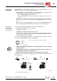
Data from
MOVIMOT
®
→
AS-i master
The following table shows the 4 data bits that are transferred from MOVIMOT
®
to the
AS-i master via the AS-Interface:
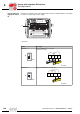
Setpoint scaling
via parameter bits
The following table shows the parameter bits for setpoint scaling. The setpoint scaling
only acts on the externally adjustable setpoint f1. Setpoint f2 and the minimum frequen-
cy are not affected by the scaling. The table shows the possible setpoint frequencies for
settings f1 = 100 Hz and f1 = 50 Hz as examples.
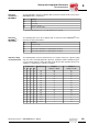
Bit Function
D0 CW / Stop
D1 CCW / Stop
D2 Speed f2 / speed f1
D3 Reset
1)
/ controller enable
1) with signal edge change from "0" → "1" (only effective in case of a fault)
Bit Function
D0 Ready message
D1 -
D2 Sensor input 1 (terminal DI 2 or optionally M12 socket pin 4)
D3 Sensor input 2 (terminal DI 3 or optionally M12 socket pin 2)
Parameter bits Divider factor Example 1 Example 2
P3 P2 P1 P0 Setting f1 = 100 Hz Setting f1 = 50 Hz
1 1 1 1 1.00 100 50
1 1 1 0 1.11 90 45
1 1 0 1 1.25 80 40
1 1 0 0 1.43 70 35
1 0 1 1 1.67 60 30
1 0 1 0 2.00 50 25
1 0 0 1 2.22 45 22.5
1 0 0 0 2.50 40 20
0 1 1 1 2.86 35 17.5
0 1 1 0 3.33 30 15
0 1 0 1 4.00 25 12.5
0 1 0 0 5.00 20 10
0 0 1 1 6.67 15 7.5
0 0 1 0 10.00 10 5
0 0 0 1 14.30 7 3.5
0 0 0 0 20.00 5 2.5
00
I