
Manual

Martin Engineering M3286-8/01 10 MOTOMAGNETIC
®
Electric Vibrators
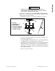
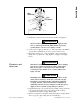
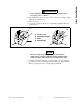
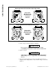
Figure 5. Wiring Diagrams
Low Voltage High Voltage
3-phase
power supply
Ground Ground
W2
U2
V2
U1 V1 W1
U1 V1 W1
W2 U2 V2
DIAGRAM 2A
Diagram 2A
Ground
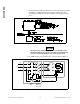
3-phase
power supply
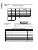
460 V
230 V
123
45 6
789
123
456
789
DIAGRAM 2C60 HZ
Diagram 2C
3-phase
power supply
3-phase
power supply
Ground
U1 V1 W1
W2 U2 V2
G L1 L2 T1 T2 T3
Hot
Neutral
3-wire cord
115V, 60Hz
power supply
U1 V1 W1
W2 U2 V2
G L1 L2 T1 T2 T3
Hot
Neutral
3-wire cord
115V, 60Hz
power supply
4-wire
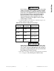
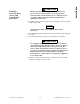
Diagram 1A
Rotation in one direction Rotation in opposite direction
cord
4-wire
cord
U1
V1 W1
W2 U2
V2
U1 V1 W1
W2
U2
V2
Diagram 1E
G L1 L2 T1 T2 T3
Hot
Neutral
3-wire cord
115V, 60Hz
power supply
G L1 L2 T1 T2 T3
Hot
Neutral
3-wire cord
115V, 60Hz
power supply
4-wire
Rotation in one direction
Rotation in opposite direction
cord
4-wire
cord
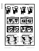
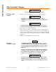
Diagram 5A
Low Voltage
High Voltage
3-phase
power supply
Ground
W2 U2 V2
U1 V1 W1
W2 U2 V2
DIAGRAM 5A
To control
module
Thermistor
U1 V1 W1
Ground
3-phase
power supply
To control
module
Thermistor
60 HZ
3-phase
power supply
3-phase
power supply
Ground
DIAGRAM 5B
To control
module
Thermistor
Ground
To control
module
1
2
3
4
5
6
7
8
9
230 V
123
456
789
Thermistor
460 V
Diagram 5B
P1 P2
W2 U2 V2
U1 V1
W1
P1P2
W2 U2 V2
U1 V1
W1
Cable Entry
Y - High Voltage s - Low Voltage
Thermostat Connection Diagram to Terminal Board
G
G
CDX Model, 6-lead, 3-phase
4
75 8 6
9
123
UV
W
47586912 3
U
V
W
Cable Entry
Y (S) - High Voltage YY - Low Voltage
9700 K Thermostat Connection Diagram to Terminal Board
GG
P1P2
P1P2
CDX Model, 9-lead, 3-phase
switch
box
switch
box
switch
box
switch
box
Installation