
Manual

Martin Engineering M3286-8/01 8 MOTOMAGNETIC
®
Electric Vibrators
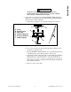
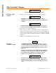
Nut and cap screw
torque
After removing any nuts or cap screws from vibrator assembly, re-install to
the torque values specified in Table II.
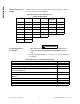
Table II. Vibrator Nut and Cap Screw
Torque Requirements
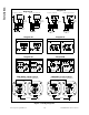
Connecting power
to vibrator
WARNING
!
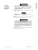
Wire vibrator in accordance with National Electrical Code
Article 430. Have wiring installed by a qualified electrician
only.
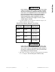
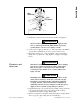
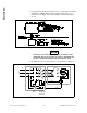
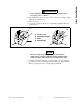
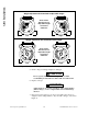
1. Find wiring diagram number for your vibrator on vibrator nameplate, or
see Table III.
Table III. Vibrators and Wiring Diagrams
Cap Screws ft/lb (kgm) Shaft Nuts ft/lb (kgm)
Terminal
Block Nuts
ft/lb (kgm)
M6 7 (1) M13x1 22 (3) M4 0.87 (0.12)
M8 16.5 (2.3) M15x1 36 (5) M5 1.45 (0.20)
M10 35 (4.8) M20x1 72 (10) M6 2.17 (0.30)
M12 58 (8) M25x1.5 123 (17) M8 4.70 (0.65)
M14 94 (13) M30x1.5 246 (34) M10 9.80 (1.35)
M16 137 (19) M45x1.5 360 (50)
M18 195 (27)
M20 275 (38)
Frame Size* Wiring Diagrams
00 through 01, single-phase, 3600 rpm Diagram 1A
10 through 30, singe-phase, 3600 rpm Diagram 1E
00 through 70, three-phase, 1200, 1800, and 3600 rpm; CD9-570;
and 575-volt 900 rpm
Diagram 2A
40 through 70, three-phase, 900 rpm except 575V Diagram 2C
80 through 110, three-phase, 1200, 1800, and 3600 rpm; and 575V
900 rpm
Diagram 5A
80 through 110, three-phase, 900 rpm except 575V Diagram 5B
CDX models CDX 6- or 9-Lead
*See “Part Numbers” section for specific model numbers.
Installation