MOTOMAGNETIC ® Electric Vibrators ® OPERATOR’S MANUAL MARTIN ®
Important Martin Engineering hereby disclaims any liability for injuries or damage resulting from use or application of this product contrary to instructions and specifications contained herein. Martin Engineering’s liability shall be limited to repair or replacement of product shown to be defective. Observe all safety rules given herein along with owner and Government standards and regulations. Know and understand lockout/tagout procedures as defined by American National Standards Institute (ANSI) z244.
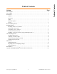
Section Page List of Figures . . . . . . . . . . . . . . . . . . . . . . . . . . . . . . . . . . . . . . . . . . . . . . . . . . . . . . . . . . . . . . . . . . . ii List of Tables . . . . . . . . . . . . . . . . . . . . . . . . . . . . . . . . . . . . . . . . . . . . . . . . . . . . . . . . . . . . . . . . . . . . ii Introduction . . . . . . . . . . . . . . . . . . . . . . . . . . . . . . . . . . . . . . . . . . . . . . . . . . . . . . . . . . . . . . . . . . . . . 1 General . . . . . . . . . . . . . . .
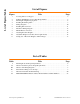
List of Figures/Tables List of Figures Figure 1 2 3 4 5 6 7 8 9 10 11 Title Page Locating Vibrator on Hoppers. . . . . . . . . . . . . . . . . . . . . . . . . . . . . . . . . . . . . . . . . . . . . . 4 W-Beam, ECF Bracket, and Locking Wedge Mounts. . . . . . . . . . . . . . . . . . . . . . . . . . . . 5 Mounting Bolt Tightening Sequence . . . . . . . . . . . . . . . . . . . . . . . . . . . . . . . . . . . . . . . . 6 Installing Restraining Cable . . . . . . . . . . . . . . . . . . . . . . . . . . . . .
General MARTIN® MOTOMAGNETIC® Electric Vibrators (CD models) are designed and manufactured to ensure the best performance and reliability in severeduty applications. The vibrator motor has a recommended operational ambient temperature and mounting surface temperature range of -22 to 104° F (-30 to 40° C). If operating the motor in environments beyond these temperatures, call Martin Engineering, as the vibrator may require rating reduction, more frequent lubrication, or lubrication substitution.
Introduction Materials required In addition to metric hand tools, the following materials are required to install this equipment: • Rigid beam or mounting plate. • BBAC Cable Kit, P/N 32271, or equivalent. (Mount Kit for Electric Vibrators, P/N 32401-XX includes W-Beam Mount, mounting hardware, and BBAC Safety Cable Kit.) Storage Martin Engineering M3286-8/01 Store vibrator in an ambient temperature not less than 41°F (5°C) with a relative humidity not more than 60%.
IMPORTANT The delivery service is responsible for damage occurring in transit. Martin Engineering CANNOT enter claims for damages. Contact your transportation agent for more information. 1. Inspect shipping container/pallet for damage. Report damage to delivery service immediately and fill out delivery service’s claim form. Keep any damaged goods subject to examination. 2. Remove vibrator from shipping container/pallet. 3. If anything is missing contact Martin Engineering or a representative.
Installation Installing Vibrator IMPORTANT Read entire section before beginning work. This manual provides instructions for installations onto steel bins and hoppers only. For other installations, call Martin Engineering or a representative. ! CAUTION If installation instructions are not followed, structure and vibrator can be damaged. Abusing or handling vibrator carelessly will accelerate wear and shorten bearing life. Mounting vibrator onto structure 1. See Figure 1.
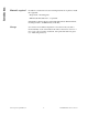
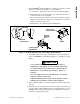
Skip weld ECF bracket P/N 29383-XX Vibrator mounting holes W-Beam P/N 29757-XX T-beam Locking wedge P/N 28309-XX Figure 2. W-Beam, ECF Bracket, and Locking Wedge Mounts 4. If installing vibrator onto hopper with female wedge mount already in place, use MARTIN® Locking Wedge (Figure 2) or equivalent to mount vibrator. ! CAUTION Never weld structure with vibrator mounted and wired. Welding may cause damage to motor windings and bearings. Use only new Grade 5 bolts and lock nuts to install vibrator.
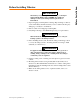
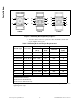
Installation 4 1 2 3 4 Bolts 3 6 1 2 5 4 5 8 3 2 1 4 7 6 6 Bolts 8 Bolts Figure 3. Mounting Bolt Tightening Sequence 7. After the vibrator has been operated for 10 to 20 minutes, check bolt torque. Tighten if necessary. Table I. Mounting Bolts and Torque Requirements* English Vibrator Type Frame Size* Metric Bolt Size (Gr 5) Dry Torque (ft-lb) Bolt Size Dry Torque (kgm) CD, CDS 00, 01 5/16 in. -18NC 17 M8 2 CD, CDS 10, 20 1/2 in.
WARNING If vibrator is mounted more than 6 in. (152 mm) above ground, install cable securing vibrator to structure. Without cable, vibrator could fall and cause injury. 8. Secure vibrator to structure by installing MARTIN® BBAC Cable Kit, P/N 32271, or equivalent as follows (cable is included with Mount Kit for Electric Vibrators, P/N 32401-XX): a. Weld D-ring (A, Figure 4) onto structure wall (B) above vibrator. C A. B. C. D. E. F.
Installation Nut and cap screw torque After removing any nuts or cap screws from vibrator assembly, re-install to the torque values specified in Table II. Table II. Vibrator Nut and Cap Screw Torque Requirements Cap Screws ft/lb (kgm) Shaft Nuts ft/lb (kgm) Terminal Block Nuts ft/lb (kgm) M6 7 (1) M13x1 22 (3) M4 0.87 (0.12) M8 16.5 (2.3) M15x1 36 (5) M5 1.45 (0.20) M10 35 (4.8) M20x1 72 (10) M6 2.17 (0.30) M12 58 (8) M25x1.5 123 (17) M8 4.70 (0.65) M14 94 (13) M30x1.
CAUTION Before running cord to vibrator, make sure cord voltage rating equals or exceeds the voltage at which you will be operating the vibrator. It must have a minimum temperature rating of 221°F (105°C) and a minimum diameter as shown in Table IV. If wire is not proper diameter, cord grip will not tighten properly and vibrator could be damaged by moisture or material getting inside wiring compartment. If cord is damaged, it could short power supply or short to ground causing damage to vibrator. 2.
U2 V2 W2 U2 V2 U1 V1 W1 U1 V1 W1 cord 4-wire W2 cord 4-wire G L1 L2 T1 T2 T3 G L1 L2 T1 T2 T3 V1 V2 W2 W1 U1 3-wire cord 3-wire cord Diagram 2C 60 HZ U2 V2 460 V 230 V 3-phase power supply V1 W1 Ground U1 V1 W1 6 7 8 9 1 2 3 3-phase power supply 3-phase power supply Ground 5 Diagram 5A To control module W2 U2 V2 7 U1 V1 W1 1 3-phase power supply To control module U1 8 9 2 3 U2 G U1 V1 DIAGRAM 5B 5 6 7 8 9 2 3 1 460 V Thermistor 3-phase
Installation Wire connector Flat washers Figure 6. Installing Wire Connector 4. Install wire connector between the two flat washers. See Figure 6. ! WARNING Vibrator must be grounded using the power supply ground wire (or other if specified in the NEC). Failure to properly ground vibrator can cause severe injury or death. 5. Connect power supply ground wire (or other if specified in the NEC) to ground vibrator terminal. Use closed loop wire connector only. 6.
Installation 3. For diagrams 5A and 5B, wire thermistor to control module in accordance with Figure 7. (Martin Engineering recommends using the control module shown in Figure 7, but other suitable control modules may be used.) Figure 7. Thermistor Wiring Diagram NOTE The thermostat terminals on CDX units are identified as P1 and P2. The thermostat circuit is rated 600 Vac maximum and 720 VA. A manual momentary start switch must be used. 4. For CDX vibrators, wire thermostats to control circuit.
Installing overload, shortcircuit, and ground-fault protection CAUTION Install overload protection for vibrator. If vibrator is not protected from overload, vibrator can be destroyed and warranty will be void. Determine size of overload protection according to NEC Article 430, and have it installed by a qualified electrician only. 1. Determine overload, short-circuit, and ground-fault protection according to NEC Article 430. NOTE All single-phase vibrators are supplied with overload protection. 2.
After Installation After Installing Vibrator IMPORTANT Read entire section before beginning work. Checking shaft rotation 1. Remove cap screws and washers, and remove vibrator end cap. ! CAUTION DO NOT run vibrator with eccentric weights removed. Running vibrator with eccentric weights removed will damage bearings. ! WARNING When checking shaft rotation with end cap removed, keep hands away from swinging weights. Weights can crush fingers. 2. Start vibrator for one second, then stop. 3.
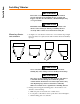
WARNING Before adjusting eccentric weights, turn off and lock out/tag out energy source to vibrator. 1. Turn off and lock out/tag out energy source to vibrator according to ANSI standards (see “References”). 2. Remove end cap. 3. Loosen nut or screw (A, Figure 9) so adjustable weight (B) will rotate around shaft (C). A A C B A. B. C. D. Nut or screw Adjustable weight Shaft Fixed weight C D D B Figure 9. Adjusting Eccentric Weights NOTE The fixed weight is attached to the shaft.
Weight adjustment disk attached to adjustable weight 0 10 0 Left 50 0 Arrow shows direction to turn adjustable weight to increase unbalance 10 50 0 Right Weight adjustment disk attached to fixed weight Arrow shows direction to turn adjustable weight to increase unbalance Left 0 0 After Installation . Right Figure 10. Adjustable Weights Set at 50% (fixed weight shaded) 5. Check o-rings for damage. Replace if damaged. ! CAUTION Do not operate vibrator with end caps removed.
After Installation Figure 11. Setting Sets of Eccentric Weights to Mirror Images Initial start up/ checking line current 1. Close power supply disconnect switch and allow motor(s) to operate for 10 to 20 minutes. 2. If vibrator makes unusual or excessive noise, make sure mounting bolts are tight and mount welds are not damaged. ! WARNING Vibrator may produce loud noise during operation when mounted on structure. See OSHA 1910.95 for guidelines.
After Installation ! Variable frequency inverter CAUTION All motors can be supplied with a pulse-width modulated variable frequency inverter. NEVER operate the motor at a frequency higher than that specified on the nameplate. Damage to vibrator can result. Do not operate vibrator motor at frequency higher than specified on nameplate. Throughout frequency range, verify that each line current does not exceed current rating on nameplate. If reading is higher than nameplate, consult inverter manual.
IMPORTANT Read entire section before beginning work. Allow vibrator to cool to ambient temperature before working on it. NOTE All vibrators are lubricated at the factory. ! CAUTION Use only prescribed grease in vibrator. If a different grease is used, vibrator can be damaged and warranty will be void. Use only prescribed amount of grease to lubricate vibrator. Too much grease will cause bearings to overheat and result in premature bearing failure. Lubricating vibrator 1.
Maintenance Table V.
Repairing motor and replacing bearings CAUTION Do not attempt to repair vibrator motor or replace bearings yourself. If you attempt to do so during the warranty period, the warranty may be void. If vibrator motor needs repair or if bearings need to be replaced, call Martin Engineering at 800-544-2947 for instructions. Inspecting vibrator At least quarterly, inspect vibrator, cable and connections as follows: ! WARNING Before inspecting vibrator, turn off and lock out/tag out energy source to vibrator.
Part Numbers Part Numbers This section provides part numbers for the S90 Series MOTOMAGNETIC® Electric Vibrators and related equipment. Please reference part numbers when ordering parts. Table VI. MOTOMAGNETIC® Electric Vibrator Model Numbers and Part Numbers 00 Frame 01 Frame Model Part No. CD18-80 601144 CD36-210 600177 CDS36-210 600177 Model 20 Frame Part No.
Cradle Lug Bracket: P/N 28732. Locking Wedge Bracket for CD36-210, CD36-390, CD36-1040, CDS36-210, CDS36-390, and CDS36-1040: P/N 28309-01. Locking Wedge Bracket for CD36-650, CD36-1660, CDS36-650, and CDS36-1660: P/N 28309-02. ECF Bracket for CD36-210, CD36-390, CD36-1040, CDS36-210, CDS36-390, and CDS36-1040: P/N 29383-01. ECF Bracket for CD36-650, CD36-1660, CDS36-650, and CDS36-1660: P/N 29383-02. W-Beam Mount: P/N 29757-XX. XX indicates vibrator frame size (see chart below).
Part Numbers Martin Engineering M3286-8/01 Frame sizes: 00 & 01 CD and CDS part numbers: 600177 600178 601144 601145 24 3 22 14 19 15 21 MOTOMAGNETIC® Electric Vibrators 23 24 25 35 36 34 33 27 28 26 39 29 30 31 1 6 32 32 22 3 6 10 2 13 7 13 10 37 24 25 23 21 15 19 14
Martin Engineering M3286-8/01 35 36 34 33 Frame sizes: 10 & 20 CD and CDS part numbers: 600179 600180 601146 601147 601198 602098 602169 602170 602883 25 14 19 15 21 27 28 26 39 13 13 7 13 37 21 15 19 14 17 15 19 32 32 29 30 12 31 22 3 11 9 6 24 25 16 23 20 14 16 17 10 1 6 2 13 22 9 7 11 16 17 12 10 MOTOMAGNETIC® Electric Vibrators 3 23 25 24 16 17 14 19 15 20 Part Numbers
Part Numbers Martin Engineering M3286-8/01 Frame sizes: 30, 33, & 50 CD and CDS 23 45 part numbers: 600181 600243 600254 600256 600257 601148 602082 602816 24 25 14 15 42 26 CDX part numbers: 600182 601149 602083 602817 MOTOMAGNETIC® Electric Vibrators 23 21 41 44 13 13 8 13 35 36 34 28 26 29 30 31 39 1 6 2 14 7 19 9 15 22 3 21 41 15 19 14 38 12 10 11 9 6 37 11 12 10 38 3 22 24 25 23 33 32 32 27 1
Martin Engineering M3286-8/01 35 36 34 Frame sizes: 35, 40, 50, & 60 CD part numbers: 600216 601201 601217 601219 601220 601227 602150 602161 602162 602165 602865 602888 602889 602890 50 49 51 33 32 32 27 6 2 11 40 6 9 27 14 19 15 41 21 5 4 MOTOMAGNETIC® Electric Vibrators 16 17 19 15 20 23 25 24 10 12 38 3 22 14 16 17 13 7 13 9 40 11 24 16 17 15 19 18 29 38 30 12 31 10 28 26 39 13 7 13 21 41 15 19 14 1 22 4 5 3 25 23 20 14 16 17 37 Part Numbers
Part Numbers Martin Engineering M3286-8/01 Frame sizes: 70, 80, 90, 95, 97, 100, 105, & 110 CD part numbers: 28 600199 600200 600201 600212 600219 601165 601166 601204 601205 601211 601221 602091 602092 602093 602134 602136 602137 602138 602142 602143 602144 602154 602167 602826 5 4 14 602827 602828 602862 602863 602870 602871 602872 602873 602884 602891 66 38 27 28 26 29 30 31 50 49 51 35 36 34 33 32 32 37 38 10 7 13 47 48 18 15 6 13 46 48 47 2 6 46 1 52 40 65 59 MOTOMAGNETIC® Electric
Frame Size and Part Number Martin Engineering M3286-8/01 S90 Vibrator (CD, CDS) 00 Description 01 10 20 29 MOTOMAGNETIC® Electric Vibrators Item 600177 601144 600178 601145 600179 601146 602169 602170 Case Flange O-Ring Shaft 1 3 6 7 * 301140 508630 400201 * 301140 508630 400201 * 301141 508615 400202 * 301141 508615 400202 * 301142 508555 400203 * 301142 508555 400204 * 301142 508555 400203 * 301142 508555 400204 Bushing, Shaft Bearing Seal, Grease Seal, Shaft Key Weight, Fixed 50
Part Numbers Frame Size and Part number S90 Vibrator (CD, CDS) Martin Engineering M3286-8/01 35 Description 30 MOTOMAGNETIC® Electric Vibrators Case Flange Screw Washer, Schnorr O-Ring Shaft Bushing, Shaft Bearing Key Weight, Fixed 50 Hz Weight, Fixed 60 Hz Weight, Adj 50 Hz Weight, Adj 60 Hz Screw Washer, Schnorr Disc, Weight Adj 50 Hz Disc, Weight Adj 60 Hz Ring, Snap Nut, Shaft O-Ring Cover, Weight 50 Hz Cover, Weight 60 Hz Screw Washer, Schnorr Terminal Block Terminal Block U.S. Screw Screw, U.S.
Frame Size and Part Number S90 Vibrator (CD, CDS) 70 Martin Engineering M3286-8/01 Description 31 MOTOMAGNETIC® Electric Vibrators Case Flange Screw Washer, Schnorr O-Ring Shaft Bushing, Shaft Bearing Seal, Grease Seal, Shaft Key Weight, Fixed 50 Hz Weight, Fixed 60 Hz Weight, Adj 50 Hz Weight, Adj 60 Hz Screw Washer, Schnorr Washer, Brass Disc, Weight Adj 50 Hz Disc, Weight Adj 60 Hz Ring, Snap Nut, Shaft O-Ring Cover, Weight 50 Hz Cover, Weight 60 Hz Screw Washer, Schnorr Terminal Block Terminal Block
Part Numbers Frame Size and Part Number S90 Vibrator (CD, CDS) 95 Martin Engineering M3286-8/01 Description 32 MOTOMAGNETIC® Electric Vibrators Case Flange Screw Washer, Schnorr Shaft Shaft, 60 Hz Bearing Key Weight, Fixed 50 Hz Weight, Fixed 60 Hz Weight, Adj 50 Hz Weight, Adj 60 Hz Screw Washer, Schnorr Washer, Brass Disc, Weight Adj 50 Hz Disc, Weight Adj 60 Hz Ring, Snap O-Ring Cover, Weight 50 Hz Cover, Weight 60 Hz Screw Washer, Schnorr Terminal Block Terminal Block U.S. Screw Screw, U.S.
Frame Size and Part Number Martin Engineering M3286-8/01 S90 Vibrator (CDX) 30X 40X 50X 60X 33 MOTOMAGNETIC® Electric Vibrators Description Item 600182 601149 602083 602817 600183 601150 602084 602818 600184 601151 601196 602085 602819 600215 601187 602122 602853 Case Flange Screw Washer, Schnorr O-Ring Shaft Bushing, Shaft Bearing Key Weight, Fixed 50 Hz Weight, Fixed 60 Hz Weight, Adj 50 Hz Weight, Adj 60 Hz Screw Washer, Schnorr Washer, Brass Disc, Weight Adj 50 Hz Disc, Weight
Part Numbers Frame Size and Part Number Martin Engineering M3286-8/01 S90 Vibrator (CDX) 70X Description 34 MOTOMAGNETIC® Electric Vibrators Case Flange Screw Washer, Schnorr O-Ring Shaft Bushing, Shaft Bearing Seal, Shaft Key Weight, Fixed 50 Hz Weight, Fixed 60 Hz Weight, Adj 50 Hz Weight, Adj 60 Hz Screw Washer, Schnorr Washer, Brass Disc, Weight Adj 50 Hz Disc, Weight Adj 60 Hz Ring, Snap O-Ring Cover, Weight Screw Washer, Schnorr Terminal Block 50 Hz Terminal Block 60 Hz Screw Washer, Schnorr Screw
Appendix Appendix MOTOMAGNETIC® Electric Vibrator Dimensions Martin Engineering M3286-8/01 A-1 MOTOMAGNETIC® Electric Vibrators
Martin Engineering M3286-8/01 A-2 MOTOMAGNETIC® Electric Vibrators 11.73 (298) 15.00 (381) 15.00 (381) 14.21 (361) 17.13 (435) 19.69 (500) 22.36 (568) 24.29 (617) 10.59 (269) 10.83 (275) 26.22 (666) 12.95 (329) 12.20 (310) 28.74 (730) 14.17 (360) 13.39 (340) 29.13 (740) 14.57 (370) 15.35 (390) 10 20 30 33 35 40 50 60 70 80 90 E 3.54 (90) 42.13 (1070) 17.87 (454) 20.87 (530) 44.09 (1120) 20.71 (526) 22.44 (570) 45.28 (1150) 23.90 (607) 24.02 (610) 105 110 2.76 (70) 0.
Get Maximum Performance from your Martin Engineering Systems! Guarantee system performance and satisfaction with installation and maintenance from Martin Services Levels of Guarantee From Martin Services Let You Match Your Needs, And Pick Your Preference Martin Services can provide economical, and efficient installation and timely service, to help you improve performance, streamline maintenance, and control costs.
Martin Engineering Mission To make bulk materials handling cleaner, safer, and more productive. One Martin Place Neponset, IL 61345-9766 USA Phone: 800-544-2947 or 309-594-2384 FAX: 309-594-2432 Form No.