
Operation Manual


16
ENGLISH
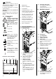
6.1 LED Indicators
− LED check:
When turning On a LED check is
carried out.
Both indicators are illuminated for
one second (LED check). As soon
as the yellow LED "Overload" extin-
guishes the machine is operational.
− Green LED "Mains" illuminated.
Machine is operational.
− Yellow LED "Overload" flashes.
Overload protection tripped. When
the yellow LED extinguishes, weld-
ing can resume.
− Green LED "Mains" flashes.
The gun's trigger switch was
pressed and held during an over-
load period. Release trigger switch:
The machine is operational again.
The trigger switch was pressed
twice too quickly.
Press trigger switch again.
6.2 Setting the Welding
Parameters
The operational parameters are set at
the control panel.
Wire feed
With the wire feed potentiometer the
speed of the wire feed is adjusted.
Wire feed setting range:
− approx. 0... 20 m/min.
On the MIG/MAG 150/20 XT, MIG/MAG
165 SP the wire feed speed depends
also on the set welding step.
Welding current (voltage)
The welding current (voltage) is set with
the welding step selector switch:
MIG/MAG 150/20 XT
− 6 steps
MIG/MAG 170/30 XTC (Combi),
MIG/MAG 165 SP
12 steps
− 6 steps at 230 V
− 6 steps at 400 V
MIG/MAG 200/40 XT, MIG/MAG 250/60
XT, MIG/MAG 300/45 XT
12 steps
− 2 coarse steps
− 6 fine steps
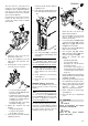
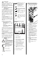
6.3 Backburn Time
When correctly set the backburn time
prevents the electrode wire from sticking
to the weld pool. Setting is adjusted by
the backburn time potentiometer (51).
− Backburn time potentiometer knob
(51) turned fully to the
left = minimum backburn time.
− Backburn time potentiometer knob
(51) turned fully to the
right = maximum backburn time.
6.4 Gas-shielded Arc Weld-
ing
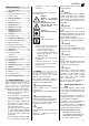
A
Caution!
Always check before starting work:
− Correct electrode wire installed?
− Correct shielding gas connected?
− Gun correctly equipped (liner, spi-
ral, tip/shroud and guide tube)?
1. Attach earth cable at a suitable loca-
tion to the workpiece.
2. Open cylinder valve and set desired
gas flow rate.
Change gas shroud, if necessary.
Rule of thumb for calculating the
required amount of shielding gas
Amount of shielding gas [l/min] =
10 x wire diameter [mm]
Example:
Electrode wire diameter 1 mm
required amount of shielding gas 10 l/min
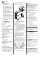
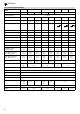
Diagram for the exact determination
of the shielding gas amount required
3. Set the welding current (voltage).
A
Caution!
Never actuate the welding current
(voltage) step switch during the run-
ning welding process.
Switching under load causes an over-
load and damages the switches.
4. Select desired operating mode.
5. Set the wire feed speed.
6. Turn machine on at the main switch.
The welding machine is now opera-
tional.
2-step mode (manual welding)
1. Press and hold trigger switch;
the welding process starts.
2. Release trigger switch;
the welding process ends.
4-step mode (continuous welding)
1. Press and release trigger switch;
the welding process starts.
2. Press and release trigger switch
again;the welding process ends.
Spot weld mode
1. Set the weld time.
2. Press trigger switch;
the spot welding starts.
The welding process ends automati-
cally after the set weld time.
3
Note:
Releasing the trigger switch
before the set weld time is over also
ends the welding process.
6.5 Shutting Down
1. Close gas cylinder valve.
2. Turn machine OFF at the main
switch.
3. Disconnect earth cable from work-
piece.
4. Unplug power cable.
This welding machine contains no user-
serviceable parts.
Depending on dust build-up it should be
blown out every 4 to 6 months with dry
compressed air.
Periodically check the machine for visi-
ble defects.
Contact a qualified electrician if any of
the cables are damaged.
For these MIG/MAG welding machines
we recommend the following accesso-
ries. They have been tested with the
machines and ensure unproblematic
operation.
51
Amount of shielding gas in l/min
Aluminium Steel
Current in A
Gas shroud diameter
in mm
7. Maintenance
8. Available Accessories