
Specifications
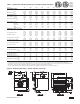

4
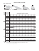
Table 1 - Performance and Dimensional Data - Tubular Propeller Unit Heater
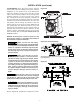
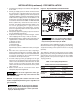
DIMENSIONS .XXX STANDARD UNITS
DIMENSIONS IN PARENTHESIS (XXX) MILLIMETERS
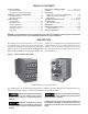
Figure 2 - Dimensional Drawing – Tubular Propeller Unit Heater
D4617C
Unit Size 100 125 150 175 200 250 300 350 400
PERFORMANCE DATA†
Input - BTU/Hr. 100,000 125,000 150,000 175,000 200,000 250,000 300,000 350,000 400,000
(kW) (29.3) (36.6) (43.9) (51.2) (58.6) (73.2) (87.8) (102.5) (117.1)
Output - BTU/Hr. 83,000 103,750 124,500 145,250 166,000 207,500 249,000 290,500 332,000
(kW) (24.3) (30.4) (36.4) (42.5) (48.6) (60.7) (72.9) (85.1) (97.2)
Thermal Effi ciency (%) 83 83 83 83 83 83 83 83 83
Free Air Delivery - CFM 1,600 2,200 2,400 2,850 3,200 3,450 5,000 5,600 5,800
(cu. m/s) (0.756) (1.039) (1.133) (1.346) (1.511) (1.629) (2.361) (2.644) (2.738)
Air Temperature Rise - °F 47 42 47 46 47 54 45 47 51
(°C) (26) (23) (26) (26) (26) (30) (24) (26) (28)
Full Load Amps at 120V 6.4 6.9 6.9 8.0 8.0 8.0 11.3 13.5 13.5
MOTOR DATA: Motor HP (Qty) 1/10 1/4 1/4 1/3 1/3 1/3 1/4 (2) 1/3 (2) 1/3 (2)
Motor kW (0.080) (0.19) (0.19) (0.25) (0.25) (0.25) (0.19) (0.25) (0.25)
Motor Type SP PSC PSC PSC PSC PSC PSC PSC PSC
RPM 1,050 1,140 1,140 1,140 1,140 1,140 1,140 1,140 1,140
Amps @ 115V 4.2 4.7 4.7 5.8 5.8 5.8 9.4 11.6 11.6
DIMENSIONAL DATA - inches (mm)
"A" Overall Height to Top of Flue 33-3/4 33-3/4 33-3/4 33-3/4 33-3/4 33-3/4 34 34 34
(857) (857) (857) (857) (857) (857) (864) (864) (864)
"B" Jacket Width of Unit 20-3/4 20-3/4 20-3/4 32-3/4 32-3/4 32-3/4 50-3/4 50-3/4 50-3/4
(527) (527) (527) (831) (831) (831) (1289) (1289) (1289)
"C" Width to CL Flue 13-3/8 13-3/8 13-3/8 19-3/8 19-3/8 19-3/8 28-3/8 28-3/8 28-3/8
(340) (340) (340) (492) (492) (492) (721) (721) (721)
"D" Depth to Rear of Housing 11 11 11 11 11 11 12-1/4 12-1/4 12-1/4
(279) (279) (279) (279) (279) (279) (311) (311) (311)
"E" Hanging Distance Width 18-5/8 18-5/8 18-5/8 30-5/8 30-5/8 30-5/8 48-5/8 48-5/8 48-5/8
(473) (473) (473) (778) (778) (778) (1235) (1235) (1235)
"F" Discharge Opening Width 18-3/4 18-3/4 18-3/4 30-3/4 30-3/4 30-3/4 48-3/4 48-3/4 48-3/4
(476) (476) (476) (781) (781) (781) (1238) (1238) (1238)
"G" Depth to CL Flue 4-3/4 4-3/4 4-3/4 4-3/4 4-3/4 4-3/4 5-1/8 5-1/8 5-1/8
(121) (121) (121) (121) (121) (121) (130) (130) (130)
"L" Overall Unit Width 25-1/4 25-1/4 25-1/4 37-1/4 37-1/4 37-1/4 55-1/4 55-1/4 55-1/4
(641) (641) (641) (946) (946) (946) (1403) (1403) (1403)
"M" Flue Size Diameter* - in 5 5 5 5 5 5 6 6 6
(mm) (127) (127) (127) (127) (127) (127) (152) (152) (152)
Fan Diameter - in (Qty) 16 16 16 18 18 18 16 (2) 18 (2) 18 (2)
Gas Inlet, Natural Gas - in 1/2 1/2 1/2 1/2 1/2 1/2 3/4 3/4 3/4
Gas Inlet, LP Gas - in 1/2 1/2 1/2 1/2 1/2 1/2 3/4 3/4 3/4
Approximate Unit Weight - lb 133 145 155 191 201 211 307 321 335
(kg) (60) (66) (70) (87) (91) (96) (139) (145) (152)
Approximate Ship Weight - lb 173 185 195 241 251 261 367 381 395
(kg) (78) (84) (88) (109) (114) (118) (166) (173) (179)
† Ratings shown are for unit installations at elevations between 0 and 2,000 feet (0 to 610m). For unit installations in U.S.A. above 2,000 feet (610m), the unit input must be fi eld derated 4% for
each 1,000 feet (305m) above sea level; refer to local codes, or in absence of local codes, refer to the latest edition of the National Fuel Gas Code, ANSI Standard Z223.1 (NFPA No. 54).
For installations in Canada, any reference to deration at altitudes in excess of 2,000 feet (610m) are to be ignored. At altitudes of 2,000 feet to 4,500 feet (610 to 1372m), the unit must be fi eld
derated and be so marked in accordance with the ETL certifi cation. See Table 6A for USA and Canadian fi eld deration information.
* Flue collar is factory supplied with unit; to be fi eld installed per included instructions. LEGEND: SP= Shaded Pole, PSC= Permanent Split Capacitor