
Specifications

4
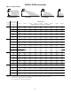
Table 1 - Performance and Dimensional Data - Separated Combustion Tubular Propeller Unit Heater
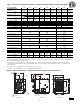
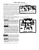
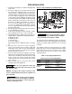
Figure 2 - Dimensional Drawing – Separated Combustion Tubular Propeller Unit Heater
D9067B
Unit Capacity (MBH) 100 125 150 175 200 250 300 350 400
PERFORMANCE DATA†
Input - BTU/Hr. 100,000 125,000 150,000 175,000 200,000 250,000 300,000 350,000 400,000
(kW) (29.3) (36.6) (43.9) (51.2) (58.6) (73.2) (87.8) (102.5) (117.1)
Output - BTU/Hr. 83,000 103,750 124,500 145,250 166,000 207,500 249,000 290,500 332,000
(kW) (24.3) (30.4) (36.4) (42.5) (48.6) (60.7) (72.9) (85.1) (97.2)
Thermal Effi ciency (%) 83
Free Air Delivery - CFM 1,600 2,200 2,400 2,850 3,200 3,450 5,000 5,600 5,800
(cu. m/s) (0.756) (1.039) (1.133) (1.346) (1.511) (1.629) (2.361) (2.644) (2.738)
Air Temperature Rise - Deg. F 47 42 47 46 47 54 45 47 51
(Deg. C) (26) (23) (26) (26) (26) (30) (24) (26) (28)
Full Load Amps at 120V 6.4 6.9 8.0 11.3 13.5
MOTOR DATA: Motor HP (Qty) 1/10 1/4 1/3 1/4 (2) 1/3 (2)
Motor kW (0.080) (0.19) (0.25) (0.19) (0.25)
Motor Type SP PSC PSC PSC PSC
RPM 1,050 1,140 1,140 1,140 1,140
Amps @ 115V 4.2 4.7 5.8 9.4 11.6
DIMENSIONAL DATA - inches (mm)
"A" Overall Height to Top of Flue 33-3/4 34
(857) (864)
"B" Jacket Width of Unit 20-3/4 32-3/4 50-3/4
(527) (831) (1289)
"C" Width to CL Flue 13-3/8 19-3/8 28-3/8
(340) (492) (721)
"D" Depth to Rear of Housing 11 12-1/4
(279) (311)
"E" Hanging Distance Width 18-5/8 30-5/8 48-5/8
(473) (778) (1235)
"F" Discharge Opening Width 18-3/4 30-3/4 48-3/4
(476) (781) (1238)
"G" Depth to CL Flue 4-3/4 5-1/8
(121) (130)
"L" Overall Unit Width 25-1/4 37-1/4 55-1/4
(641) (946) (1403)
"M" Flue Size Diameter* - in 5 6
(mm) (127) (152)
Gas Inlet, Natural Gas - in 1/2 3/4
Gas Inlet, LP Gas - in 1/2 1/2 OR 3/4
Approximate Unit Weight - lb 135 147 157 194 204 214 311 325 339
(kg) (61) (67) (71) (88) (93) (97) (141) (147) (154)
Approximate Ship Weight - lb 175 187 197 244 254 264 371 385 399
(kg) (79) (85) (89) (111) (115) (120) (168) (175) (181)
† Ratings shown are for unit installations at elevations between 0 and 2,000 ft (0 to 610m). For unit installations in U.S.A. above 2,000 ft. (610m), the unit input
must be fi eld derated 4% for each 1,000 ft. (305m) above sea level; refer to local codes, or in absence of local codes, refer to the latest edition of the National Fuel
Gas Code, ANSI Standard Z223.1 (N.F.P.A. No. 54).
For installations in Canada, any reference to deration at altitudes in excess of 2,000 ft. (610m) are to be ignored. At altitudes of 2,000 ft. to 4,500 ft. (610 to
1372m), the unit must be fi eld derated to 90% of the normal altitude rating, and be so marked in accordance with the ETL certifi cation. See Table 6A for fi eld
deration information.
* Flue collar is factory supplied with unit; to be fi eld installed per included instructions.
** LEGEND: SP = SHADED POLE PSC = PERMANENT SPLIT CAPACITOR
24-1/2
(622mm)
(Discharge
Opening)
33"
(838mm)
A
F
(Discharge
Opening)
1"
(25mm)
B
L
32-1/2'
(826mm)
D
G
11-5/8
(295mm)
(Hanging)
Gas Valve
Connection
Electrical Control Panel
C
E
(Hanging)
1-3/8'
(35mm)
(Hanging)
M
(Flue Diameter)
Rear View
Side View
Front View
High Limit
Access
Combustion Air
Inlet