
Specifications
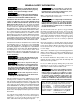
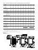
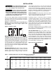
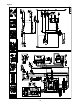

Table 1 – Performance and Specifi cation Data – Separated Combustion Propeller Unit heater
Capacity (MBH) 100 125 150 175 200 225 250 300 350 400
PERFORMANCE DATA ‡
Input BTU/Hr 100,000 125,000 150,000 175,000 200,000 225,000 250,000 300,000 350,000 400,000
(kW) (29.3) (36.6) (43.9) (51.2) (58.6) (65.9) (73.2) (87.8) (102.5) (117.1)
Output BTU/Hr 80,000 100,000 120,000 140,000 160,000 180,000 200,000 240,000 280,000 320,000
(kW) (23.4) (29.3) (35.1) (41.0) (46.9) (52.7) (58.6) (70.3) (82.0) (93.7)
Thermal Effi ciency (%) 80 80 80 80 80 80 80 80 80 80
Free Air Delivery CFM 1,480 1,650 2200 2,530 2,640 2,700 3,100 4,400 5,000 5,300
(cu. m/s) (0.699) (0.779) (1.038) (1.194) (1.246) (1.274) (1.463) (2.077) (2.360) (2.502)
Air Temperature Rise °F 50 56 50 51 56 61 60 50 52 56
(°C) (10) (13) (10) (11) (13) (16) (16) (10) (11) (13)
Outlet Velocity FPM 775 910 1045 1070 1000 950 980 1100 1150 1050
(m/s) (3.9) (4.6) (5.3) (5.4) (5.1) (4.8) (5.0) (5.6) (5.8) (5.3)
Full Load Amps at 115V (ODP) 4.5 6.1 6.6 7.7 7.7 7.7 7.7 11.3 13.5 13.5
MOTOR DATA: Motor HP 1/20 1/10 1/4 1/3 1/3 1/3 1/2 (2)1/4 (2)1/3 (2)1/3
Motor (kW) (0.037) (0.075) (0.186) (0.249) (0.249) (0.249) (0.373) (0.186) (0.249) (0.249)
Motor Type (ODP) SP SP PSC PSC PSC PSC PSC PSC PSC PSC
RPM 1,050 1,050 1,140 1,140 1,140 1,140 1,140 1,140 1,140 1,140
Amps @ 115V (ODP) 2.6 4.2 4.7 5.8 5.8 5.8 5.8 9.4 11.6 11.6
DIMENSIONAL DATA Inches (mm)
“A” Height to Top of Unit 31-1/4 31-1/4 36-1/4 36-1/4 36-1/4 36-1/4 36-1/4 36-1/4 36-1/4 36-1/4
(794) (794) (921) (921) (921) (921) (921) (921) (921) (921)
“B” Height to Top of Hanger 34-1/16 34-1/16 39-1/16 39-1/16 39-1/16 39-1/16 39-1/16 39-1/16 39-1/16 39-1/16
(865) (865) (992) (992) (992) (992) (992) (992) (992) (992)
“C” Hanging Distance Width 14-3/4 17-1/2 17-1/2 20-1/4 23 25-3/4 28-1/2 34 39-1/2 45
(375) (445) (445) (514) (584) (654) (724) (864) (1003) (1143)
“D” Discharge Opening Width 15-3/8 18-1/8 18-1/8 20-7/8 23-5/8 26-3/8 29-1/8 34-5/8 40-1/8 45-5/8
(391) (460) (460) (530) (600) (670) (740) (879) (1019) (1159)
“E” Width of Unit 17-7/8 20-5/8 20-5/8 23-3/8 26-1/8 28-7/8 31-5/8 37-1/8 42-5/8 48-1/8
(454) (524) (524) (594) (664) (733) (803) (943) (1083) (1222)
“F” to Centerline of Flue 5-7/8 7-1/4 7-1/4 8-5/8 10 11-1/4 12-3/4 15-1/2 18-1/4 21
(149) (184) (184) (219) (254) (286) (324) (394) (464) (533)
Flue Size Diameter Inches** 4 4 4 4 5 5 5 6 6 6
(Diameter mm) (102) (102) (102) (102) (127) (127) (127) (152) (152) (152)
Air Inlet Size-Inches 4 4 4 4 5 5 5 6 6 6
(mm) (102) (102) (102) (102) (127) (127) (127) (152) (152) (152)
Fan Diameter-Inches 14 16 16 18 18 18 18 16 18 18
Gas Inlet-Natural Gas-Inches 1/2 1/2 1/2 1/2 1/2 3/4 3/4 3/4 3/4 3/4
Gas Inlet-LP Gas-Inches 1/2 1/2 1/2 1/2 1/2 ← 1/2 or 3/4 →
Approx. Shipping Wt. lb. 200 228 256 284 312 340 368 432 488 545
(kg) (91) (103) (116) (129) (142) (154) (167) (196) (221) (247)
4
DIMENSIONS .XXX STANDARD UNITS
DIMENSIONS IN PARENTHESIS (XXX) MILLIMETERS
Figure 1A
‡ Ratings shown are for unit installations at elevations between 0 and 2,000 ft. (0 to 610m). For unit installations in U.S.A. above 2,000 ft. (610m), the unit input must be derated 4% for each 1,000 ft.
(305m) above sea level; refer to local codes, or in absence of local codes, refer to the latest edition of the National Fuel Gas Code, ANSI Standard Z223.1 (N.F.P.A. No. 54).
For installations in Canada, any reference to deration at altitudes in excess of 2,000 ft. (610m) are to be ignored. At altitudes of 2,000 ft. to 4,500 ft. (610 to 1372m), the unit must be derated to 90%
of the normal altitude rating, and be so marked in accordance with the ETL certifi cation.
LEGEND: SP = SHADED POLE PSC = PERMANENT SPLIT CAPACITOR ODP = OPEN DRIP PROOF