
Specifications
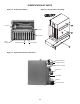
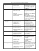
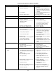
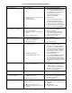
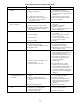
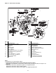
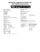


Figure 17 - Power Venter Assembly
NOTES:
*1) For item No. 6, use counter-clockwise rotation.
2) DO NOT OVERTIGHTEN CELCON NUT! HAND TIGHTEN ONLY! DO NOT USE TOOLS!
Approximate 1/3 turn maximum or 8 inch pounds is suffi cient from the point where the tube does not slip in or out.
3) Flue Sizes:
100/175 units: 4 inch dia. fl ue outlet Reducer required – To be supplied by installer.
200/250 units: 5 inch dia. fl ue outlet (no adapter required).
300/400 units: 6 inch dia. fl ue outlet Increaser required – To be supplied by manufacturer.
27
REF.
NO. DESCRIPTION
1 Blower Housing Assembly
2 Speed Nut
3 Motor
4 Washer, Plain
5 Plate Adapter
6 Blower Wheel*
7 Mounting Bracket (Pressure Switch)
8 Mounting Bracket (Junction Box)
9 Screw, S.T.
10 Screw, Machine (L =
3
/
4
inch)
11 Nut, Keps (Ext. Lock Washer)
12 Air Pressure Switch
13 Drill Screw
REF.
NO. DESCRIPTION
14 Junction Box Cover
15 Snap Bushing
16 Relay (Motor)
17 Draftor Stack Assembly
18 Tubing (Aluminum) Formation
19 Male Connector
20 Locknut
21 Hole Plug
22 Pressure Switch Cover
23 Drill Screw
24 Junction Box Base
25 Purge Relay (not shown)
- located in Junction Box